


OM-929 Page 17
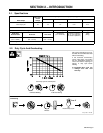
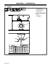
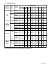
3-2. Weld Parameters
Material Thickness
Wire Type,
Shielding Gas,
And Flow Rate
Wire
Diameter
(inch)
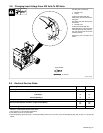
Operator
Controls
3/8 in
(9.5
mm)
1/4 in
(6.4
mm)
3/16 in
(4.8
mm)
1/8 in
(3.2
mm)
12 ga 14 ga 16 ga 18 ga 20 ga 22 ga
Voltage Tap – – 6 5 4 3 3 2 2 1 1
.023
Wire Speed – – 100 80 65 55 45 35 25 15 5
E70S-6
Voltage Tap 6 5 4 3 3 2 2 1 1 – –
CO
2
20 cfh+
.030
Wire Speed 80 70 60 55 45 35 25 15 5 – –
Voltage Tap 6 5 4 3 3 2 2 2 – – – –
.035
Wire Speed 70 60 50 45 40 30 20 10 – – – –
Voltage Tap – – 5 4 3 3 2 2 1 1 1
.023
Wire Speed – – 90 80 70 60 50 40 35 25 12
E70S-6
75% Argon
Voltage Tap 6 5 4 3 3 2 2 1 1 1
75% Argon
25% CO
2
20 cfh+
.030
Wire Speed 85 75 65 55 50 45 35 20 5 0
20 cfh+
Voltage Tap 6 5 4 3 3 2 2 1 1 – –
.035
Wire Speed 80 70 60 45 40 30 20 10 0 – –
Voltage Tap 6 5 5 4 4 3 2 1 – – – –
E71T-GS
.030
Wire Speed 80 70 65 55 50 30 20 10 – – – –
E71T-GS
Flux Core
Voltage Tap 6 5 4 3 3 2 1 – – – – – –
.035
Wire Speed 60 50 40 30 25 20 10 – – – – – –
Voltage Tap 5 4 4 4 3 3 3 2 2 2
.023
Wire Speed 95 85 80 60 50 50 50 30 20 20
ER 308
Stainless Steel
90% HE /
Voltage Tap 5 5 4 3 3 2 2 2 1 – –
90% HE /
7.5% Argon /
2.5% CO
2
.030
Wire Speed 70 70 70 50 45 50 45 40 0 – –
2
20 cfh+
Voltage Tap 6 5 5 4 3 2 2 2 – – – –
.035
Wire Speed 65 40 40 30 30 25 20 10 – – – –
*Do not change Voltage switch position while welding. Wire Speed is a starting value only, and can be adjusted while welding. Weld conditions also
depend on other variables such as stickout, travel speed, weld angle, cleanliness of metal, etc.