


OM-228 187 Page 13
SECTION 5 − INSTALLATION
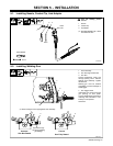
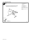
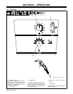
5-1. Installing Nozzle, Contact Tip, And Adapter
246 669-A
! Turn off welding power
source.
1 Nozzle
2 Contact Tip
3 Tip Adapter
. Wire size stamped on tip − check
and match wire size.
Tools Needed:
8 mm
Head
Tube
8 mm
1
3
2
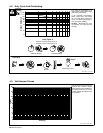
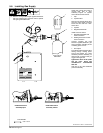
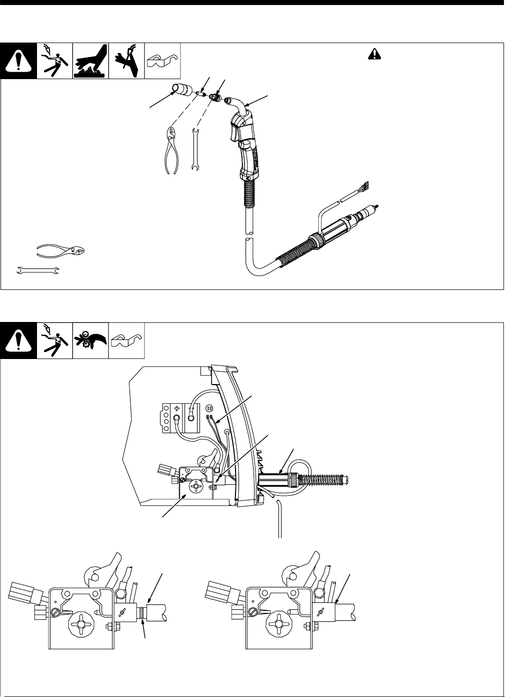
5-2. Installing Welding Gun
804 621-A
1 Drive Assembly
2 Gun Securing Thumbscrew
3 Gun End
Loosen thumbscrew. Insert end
through opening until it bottoms
against drive assembly. Tighten
thumbscrew.
Welding gun must be inserted
completely to prevent leakage of
shielding gas.
4 Gun Trigger Leads
Insert leads, one at a time, through
gun opening on front panel.
Connect female friction terminals to
matching male terminals in unit.
Polarity is not important.
Close door.
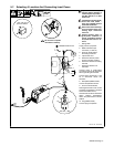
CorrectIncorrect
. Be sure that gun end is tight against drive assembly.
3
Gun Fully Seated
3
Gun Not Seated
Exposed O-rings
will cause shielding
gas leakage.
4
1
2
3