


OM-228 187 Page 18
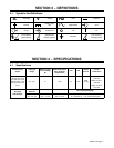
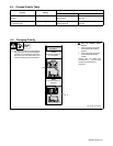
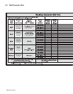
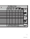
5-8. Electrical Service Guide
Failure to follow these electrical service guide recommendations could create an electric shock or fire hazard. These recommenda-
tions are for a dedicated branch circuit sized for the rated output and duty cycle of the welding power source.
Input Voltage (V)
230
Input Amperes (A) At Rated Output 20.5
Max Recommended Standard Fuse Or Circuit Breaker Rating In Amperes
Circuit Breaker
1
, Time-Delay Fuses
2
25
Normal Operating Fuses
3
30
Min Input Conductor Size In AWG 14
Max Recommended Input Conductor Length In Feet (Meters)
67
(20)
Min Grounding Conductor Size In AWG 14
Reference: 2008 National Electrical Code (NEC) (including article 630)
1 If a circuit breaker is used in place of a fuse, choose a circuit breaker with time-current curves comparable to the recommended fuse.
2 “Time-Delay” fuses are UL class “RK5” . See UL 248.
3 “Normal Operating” (general purpose - no intentional delay) fuses are UL class “K5” (up to and including 60 amps), and UL class “H” ( 65 amps and
above).
4 Conductor data in this section specifies conductor size (excluding flexible cord or cable) between the panelboard and the equipment per NEC Table
310.16. If a flexible cord or cable is used, minimum conductor size may increase. See NEC Table 400.5(A) for flexible cord and cable requirements.
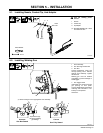
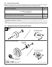
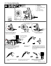
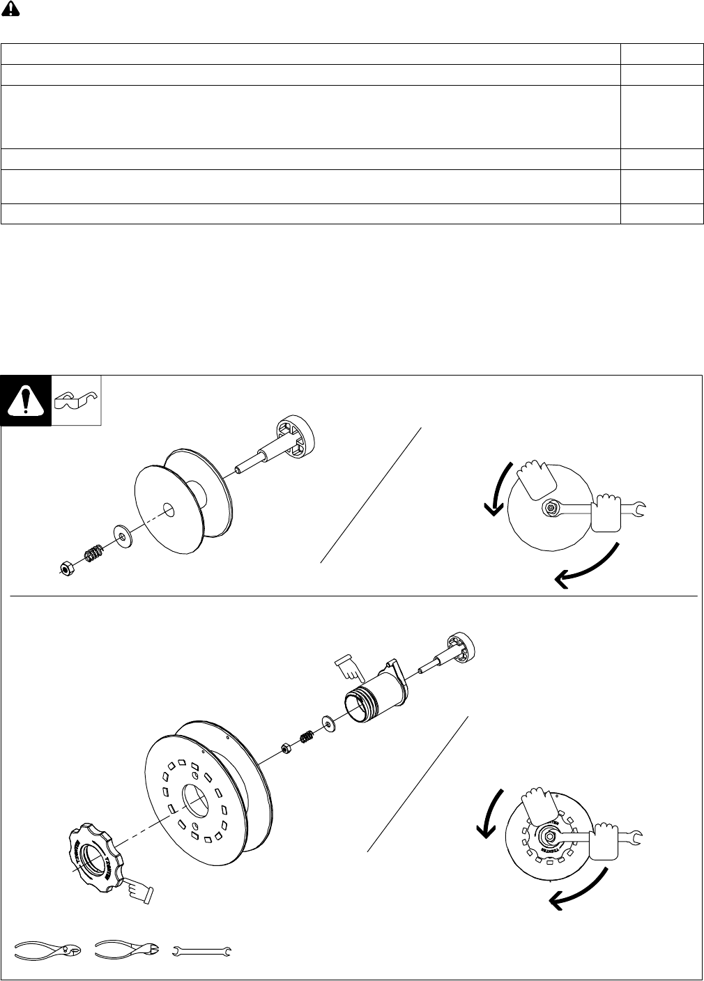
5-9. Installing Wire Spool And Adjusting Hub Tension
When a slight force is needed
to turn spool, tension is set.
1/2 in.
Tools Needed:
803 012 / 803 013 -B / Ref. 802 971-C
Installing 8 in. (203 mm) Wire Spool
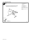
Installing 4 in. (102 mm) Wire Spool
When a slight force is needed
to turn spool, tension is set.
Retaining ring used
with 8 in. (203 mm)
spool only.
Adapter used with
8 in. (203 mm)
spool only.