


OM-492 Page 32
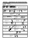
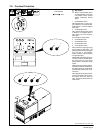
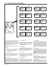
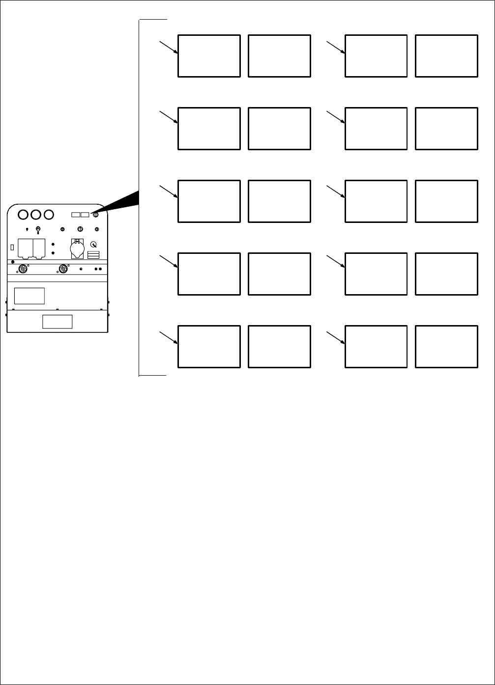
7-9. Voltmeter/Ammeter Help Displays
Use the voltmeter/ammeter help displays to
help determine the cause of no weld output.
When a help display is shown, the inverter
module weld output has stopped but the en-
gine continues to run. Correct the problem
before resuming operation.
The display screen resets when the fault is
corrected.
. All directions are in reference to the front
of the unit. All circuitry referred to is lo-
cated inside the inverter module.
1 Help 0 Display
Indicates a shorted thermistor RT2 on the left
side of the unit. If this display is shown, con-
tact a Factory Authorized Service Agent.
2 Help 1 Display
Indicates a malfunction in the primary power
circuit possibly caused by applying a high
weld load at idle speed. Turn Engine Control
switch to Run position. If problem continues,
contact a Factory Authorized Service Agent.
3 Help 2 Display
Indicates a malfunction in the thermal protec-
tion circuitry located on the left side of the unit.
If this display is shown, contact a Factory Au-
thorized Service Agent.
4 Help 3 Display
Indicates the left side of the unit has over-
heated. The unit has shut down to allow the
fan to cool it (see Section 3-3). Operation will
continue when the unit has cooled.
5 Help 4 Display
Indicates a malfunction in the thermal protec-
tion circuitry located on the right side of the
unit. If this display is shown, contact a Factory
Authorized Service Agent.
6 Help 5 Display
Indicates the right side of the unit has over-
heated. The unit has shut down to allow the
fan to cool it (see Section 3-3). Operation will
continue when the unit has cooled.
7 Help 6 Display
Indicates that the input voltage is too low and
the unit has automatically shut down. Opera-
tion will continue when the voltage is within the
acceptable lower range limit (15% below the
applicable input voltage). If this display is
shown, have a Factory Authorized Service
Agent check the power generator output volt-
age.
8 Help 7 Display
Indicates that the input voltage is too high and
the unit has automatically shut down. Opera-
tion will continue when the voltage is within the
acceptable upper range limit (15% above the
applicable input voltage). If this display is
shown, have a Factory Authorized Service
Agent check the power generator output volt-
age.
9 Help 8 Display
Indicates a malfunction in the secondary pow-
er circuit of the unit. If this display is shown,
contact a Factory Authorized Service Agent.
10 Help 9 Display
Indicates a shorted thermistor RT1 on the
right side of the unit. If this display is shown,
contact a Factory Authorized Service Agent.
1
AV
2
AV
3
AV
HE.L P–0
HE.L P–1
HE.L P–2
4
AV
HE.L P–3
5
AV
HE.L P–4
6
AV
7
AV
8
AV
HE.L P–5
HE.L P–6
HE.L P–7
9
AV
HE.L P–8
10
AV
HE.L P–9
802 174-E