


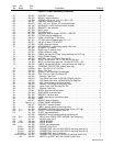
OM-492 Page 54
Description
Part
No.
Dia.
Mkgs.
Item
No.
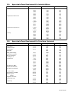
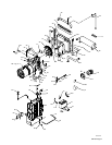
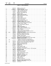
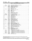
Figure 11-5. Main Assembly (Continued)
Quantity
197 535 HARNESS, wiring engine compartment (consisting of) 1. . . . . . . . . . . . . . . . . . . . . . . . . . . . . . . . . . . . .
RC15 158 466 CONNECTOR, rect univ 084 12P/S 3 row rcpt 1. . . . . . . . . . . . . . . . . . . . . . . . . . . . . . . . . . . . . .
PLG27 192 170 CONNECTOR, rect 250 2skt 1 row plug 1. . . . . . . . . . . . . . . . . . . . . . . . . . . . . . . . . . . . . . . . . .
PLG36 192 169 CONNECTOR, rect 250 1skt 1 row plug 1. . . . . . . . . . . . . . . . . . . . . . . . . . . . . . . . . . . . . . . . . .
PLG28 192 171 CONNECTOR, rect 250 3skt 1 row plug 1. . . . . . . . . . . . . . . . . . . . . . . . . . . . . . . . . . . . . . . . . .
PLG37 192 168 CONNECTOR, rect 250 1 pin 1 row rcpt 1. . . . . . . . . . . . . . . . . . . . . . . . . . . . . . . . . . . . . . . . .
PLG11 092 670 CONNECTOR, rect univ 084 3P/S 1 row plug 1. . . . . . . . . . . . . . . . . . . . . . . . . . . . . . . . . . . . .
192 167 SEAL, wire univ 3P/S 1 row 1. . . . . . . . . . . . . . . . . . . . . . . . . . . . . . . . . . . . . . . . . . . . . . . . . . . . . . . . . . . .
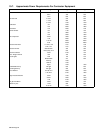
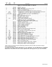
107 CB9,CB10 139 266 CIRCUIT BREAKER, man reset 1P 15A 250VAC frict (see Figure 11-5) 2. . . . . . .
108 CB8 115 427 CIRCUIT BREAKER, man reset 1P 25A 250VAC frict (see Figure 11-5) 1. . . . . . . . . . .
109 CB7 147 658 CIRCUIT BREAKER, man rest 1P 30A 250VAC screw (see Figure 11-5) 1. . . . . . . . . . .
110 CR3 197 325 RELAY, encl 12vdc spst 50a 4pin flange mtg 1. . . . . . . . . . . . . . . . . . . . . . . . . . . . . . . . . . .
111 Figure 11-7 INVERTER ASSEMBLY 1. . . . . . . . . . . . . . . . . . . . . . . . . . . . . . . . . . . . . . . . . . . . . . . . . . . . . . . .
112 198 158 PANEL, generator right 1. . . . . . . . . . . . . . . . . . . . . . . . . . . . . . . . . . . . . . . . . . . . . . . . . . . . . . . . . . .
194 126 KIT, foam 1. . . . . . . . . . . . . . . . . . . . . . . . . . . . . . . . . . . . . . . . . . . . . . . . . . . . . . . . . . . . . . . . . . . . . . . . . . . .
+When ordering a component originally displaying a precautionary label, the label should also be ordered.
*Recommended Spare Parts.
♦Optional
To maintain the factory original performance of your equipment, use only Manufacturer’s Suggested
Replacement Parts. Model and serial number required when ordering parts from your local distributor.
. Hardware is common and
not available unless listed.
802 327-B
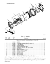
18
2
34
36
3
10
17
9
8
16
15
11
12
6
8
9
7
13
14
16
21
20
23
22
24
25
30
27
26
28
35
31
33
32
29
4
38
5
37
1
19
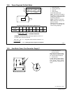
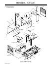
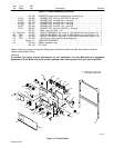
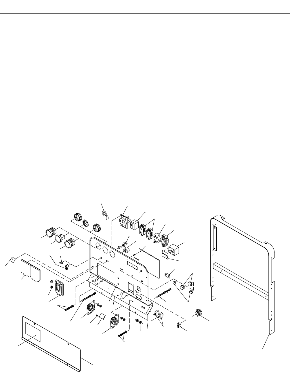
Figure 11-6. Front Panel