


OM-277 Page 12
SECTION 3 – INSTALLATION
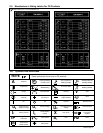
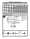
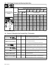
3-1. Specifications
IP
Rated Amperage/
Max
Amperes Input at Rated Load Output
50 or 60 Hz, Three-Phase
Model
IP
Rating
Welding
Output
Voltage
Range
Max
OCV–DC
200
V
230
V
380
V
400
V
440
V
460
V
520
V
575
V
KVA KW
300 A @ 32
15 – 375A
In CC Mode
60 VDC In
CC Mode
57.5
4.0*
50
3.5*
30
1.5*
28
1.4*
26
1.3*
25
1.8*
--
20
1.4*
20
1.4*
12.9
0.6*
300
Amp
21M
(29) Volts
DC, 100%
Duty Cycle
10 – 32V In
CV Mode
38 (40) VDC
In
CV Mode
69
4.0*
60
3.5*
36
1.4*
34
1.3*
31
1.2*
30
1.8*
--
24
1.4*
23.7
1.4*
13.4
0.6*
450
450 A @ 38
(36.5) Volts
20 – 565A
In CC Mode
65 (62) VDC
In
CC Mode
91
4.2*
79
3.8*
48
1.8*
46
1.6*
41
1.4*
39
1.9*
34
1.2*
31
1.5*
31.4
1.5*
22
0.7*
450
Amp
21M
(36.5) Volts
DC, 100%
Duty Cycle
10 – 38V In
CV Mode
45 (50) VDC
In
CV Mode
104
4.2*
90
3.8*
52.5
1.6*
51
1.4*
46
1.3*
45
1.9*
38
1.4*
36
1.5*
35.3
1.5*
22.3
0.7*
*While idling
( ) Indicates specification differences for CE models
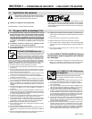
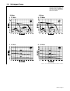
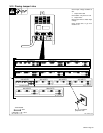
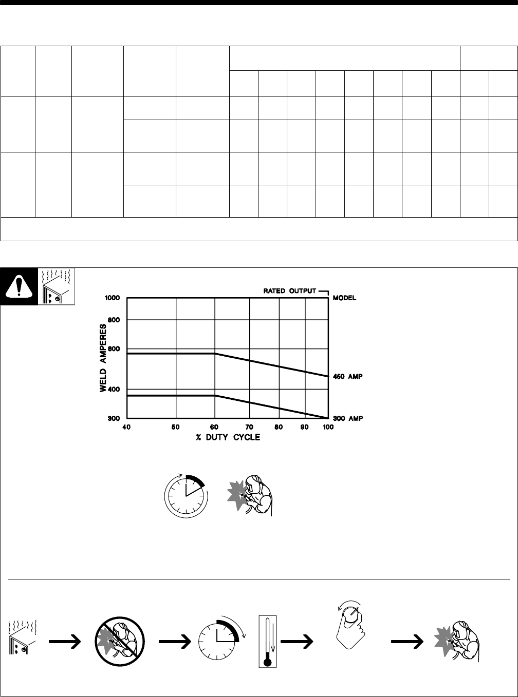
3-2. Duty Cycle And Overheating
Duty Cycle is percentage of 10 min-
utes that unit can weld at rated load
without overheating.
If unit overheats, thermostat(s)
opens, output stops, and cooling
fan runs. Wait fifteen minutes for
unit to cool. Reduce amperage or
duty cycle before welding.
Y Exceeding duty cycle can
damage unit and void
warranty.
100% Duty Cycle
Overheating
0
15
A/V
OR
Reduce Duty Cycle
Minutes
duty1 4/95 / Ref. SA-168 918
Continuous Welding