


OM-277 Page 14
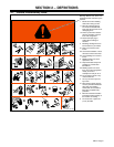
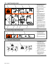
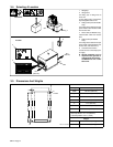
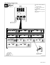
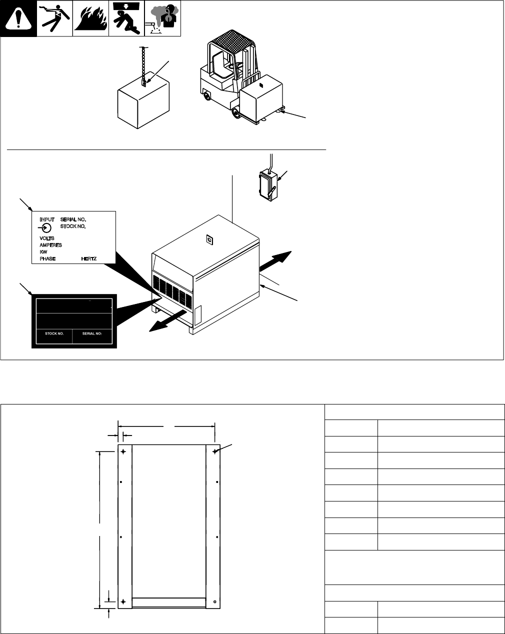
3-4. Selecting A Location
1 Lifting Eye
2 Lifting Forks
Use lifting eye or lifting forks to
move unit.
If using lifting forks, extend forks
beyond opposite side of unit.
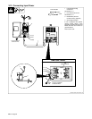
3 Rating Label (Non CE Models
Only)
Use rating label to determine input
power needs. Label located under
front access door.
4 Plate Label (CE Models Only)
Label located under front access
door.
5 Rating Label (CE Models
Only)
Use rating label to determine input
power needs. Label located on rear
access door (see Section 2-5).
6 Line Disconnect Device
Locate unit near correct input pow-
er supply.
Y Special installation may be
required where gasoline or
volatile liquids are present –
see NEC Article 511 or CEC
Section 20.
3
6
18 in
(460 mm)
18 in
(460 mm)
OR
1
2
Movement
Location
4
5
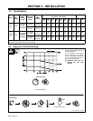
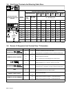
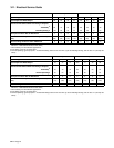
3-5. Dimensions And Weights
Dimensions
C
Height 27-1/4 in (692 mm)
D
E
Width 22-1/4 in (565 mm)
4 Holes
Depth* 35-3/4 in (908 mm)
A** 35 in (889 mm)
B*** 1-1/4 in (32 mm)
C 21 in (533 mm)
A
D 1-3/16 in (30 mm)
A
E 7/16 in (11 mm) Dia
*300 Amp Model = 28-1/4 in (718 mm)
**300 Amp Model = 27-1/2 in (699 mm)
***300 Amp Model = 3/4 in (19 mm)
Weight
300 Amp 361 lbs (164 kg)
B
Ref. ST-153 556-A
450 Amp 424 lbs (192 kg)