


OM-480 Page 22
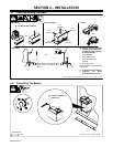
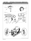
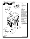
6-3. Connecting Optional Auxiliary Power Plant
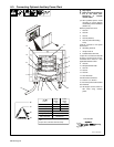
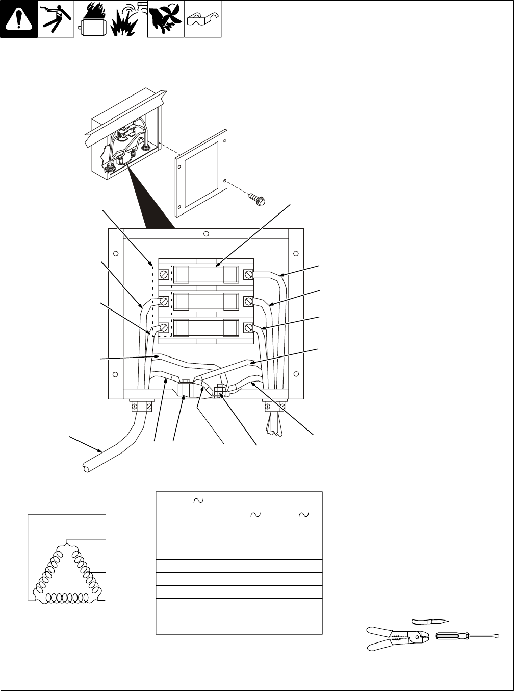
Ref. S-179 637-B
Y Stop engine.
Y Power and weld outputs are
live at the same time.
Disconnect or insulate
unused cables.
. Have qualified person install
according to circuit diagram
and Auxiliary Power Guidelines
(Section 10).
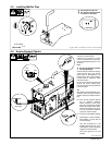
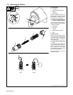
Remove junction box cover.
1 Lead 93
2 Lead 92
3 Lead 91
4 Lead 90 (Neutral)
5 Lead 42 (Circuit Grounding
Lead)
Lead 42 connects to front panel
Ground stud.
6 Grounding Terminal
7 Jumper Lead 42
8 Isolated Neutral Terminal
Jumper 42 is connected to lead 90
at factory. Jumper 42 may be dis-
connected from neutral to meet
applicable electrical codes.
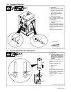
9 Lead 80
10 Receptacle RC9 leads
11 Lead 42
12 Lead 81
13 Lead 82
14 Load Terminals
Connect leads to terminals.
15 Fuses F1, F2, And F3
F1, F2, and F3 protect each load line
from overload.
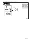
. Set Engine Control switch to
Run when using auxiliary
power.
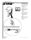
92
90
91
93
Tools Needed:
F3
F2
F1
3
5
4
678
14
15
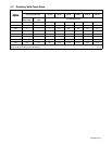
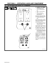
Volts
Amps
KVA/KW
Single
120/240
31
7.5
Three
240
24
10
60 HzFrequency
Engine Speed
Max. Fuse Size 35 Amperes
1850 RPM
AC
Phase
1
Phase
3
Output
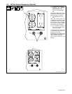
Lead 42 connects to GROUND stud on front of
unit.
Jumper 42 is connected to 90 at factory.
1
2
10
9
13
12
11