


OM-201 444 Page 19
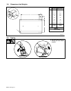
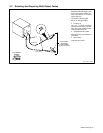
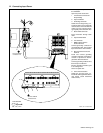
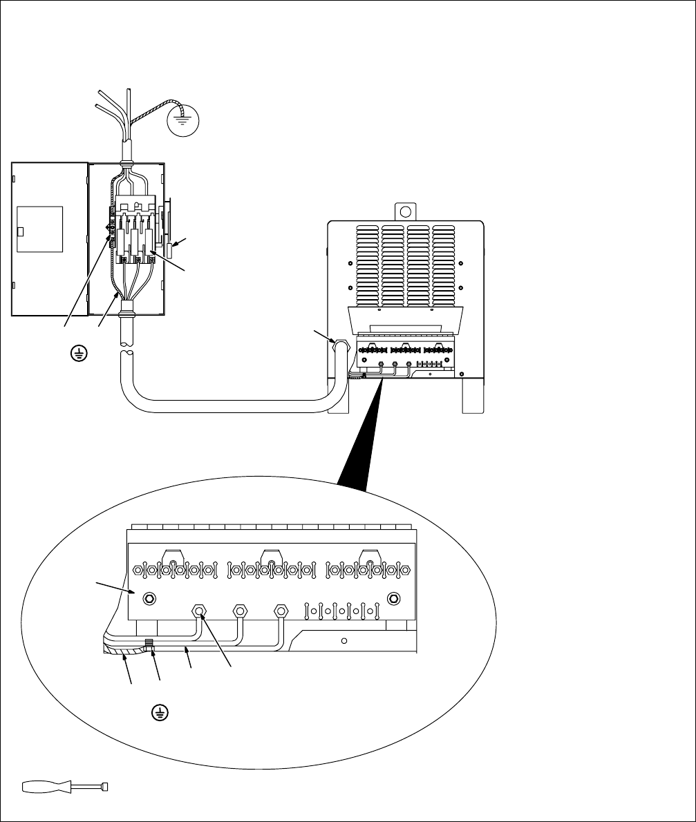
B. Connecting Input Power
Have only qualified persons make
this installation.
Open rear panel access door.
1 Line Disconnect Device Of
Proper Rating
2 Input Conductors
3 Grounding Conductor
Select size and length using 3-11.
Conductor rating must comply with
national, state, and local electrical
codes. Use lugs of proper amper-
age capacity and correct hole size.
4 Strain Relief Connector
Insert conductors through strain
relief.
5 Input Terminal Board
6 Line Terminals
7 Welding Power Source
Ground Terminal
Connect grounding conductor to
ground terminal first. Then connect
input conductors to line terminals.
8 Disconnect Device Ground
Terminal
Install and connect grounding
conductor and input conductors in
conduit or equivalent to deener-
gized line disconnect device.
Connect grounding conductor first,
then line input conductors.
Be sure grounding conductor goes
to an earth ground.
Close rear panel door.
9 Overcurrent Protection
Select type and size using 3-11.
Install into deenergized line discon-
nect device (fused disconnect
switch shown).
1
9
3
4
8
5
3
2
7
6
Tools Needed:
3/8, 7/16, 1/2 in
ssb2.4 1/94 – ST-800 042-A
Connect GND/PE
Conductor First.
Connect GND/PE
Conductor First.