


OM-201 444 Page 21
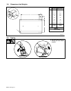
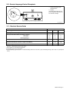
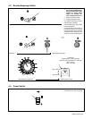
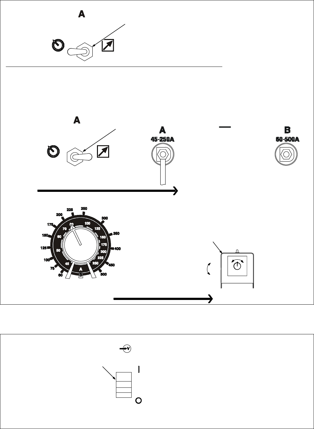
4-3. Remote Amperage Switch
1
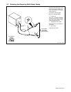
Y Arcing can damage switch.
Do not change Remote Am-
perage switch position while
power is on. Arcing inside
switch can damage con-
tacts, causing switch to fail.
1 Remote Amperage Switch
2 Remote Amperage Control
Use switch to select way of control-
ling amperage adjustment.
For front panel control, place switch
in the Panel position.
For remote control, place switch in
the Remote position and connect
remote amperage control to remote
amperage control receptacle (see
Section 3-10). See example below.
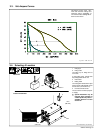
Example: Combination Remote Amperage Control – 400 Ampere Non CE Model Shown
Set Switch Select Amperage Range
Min (45 A DC)
Max (100 A DC)
2
Min = 45 A DC
Max = 100 A DC
In Example:
Range Selected = 45 to 250 A DC
Maximum Amperage Selected = 100 A DC
Adjust Remote ControlSelect Maximum Amperage
1
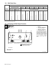
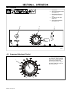
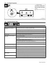
4-4. Power Switch
1
1 Power Switch
Use switch to turn unit t On and Off.