OM-499 Page 28
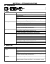
SECTION 8 – TROUBLESHOOTING
8-1. Troubleshooting
A. Welding
Trouble Remedy
No weld output. Check Amperage control setting.
Check weld connections.
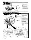
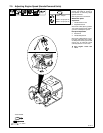
Check engine speed, and adjust if necessary (see Section 7-4 or 7-5). Output stops if engine speed is
too low.
Be sure all equipment is disconnected from receptacles when starting unit.
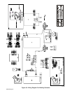
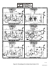
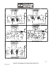
Have Factory Authorized Service Agent check brushes, slip rings, capacitor C1, integrated rectifiers
SR1 and SR2, resistor R3 (Kohler only), and circuit board PC1.
Low weld output. Check Amperage control and throttle lever settings.
Check engine speed, and adjust if necessary (see Section 7-4 or 7-5).
Service air cleaner according to engine manual.
Check weld cable size and length.
Have Factory Authorized Service Agent check brushes, slip rings, capacitor C1, integrated rectifiers
SR1 and SR2, resistor R3 (Kohler only), and circuit board PC1.
High weld output. Check Amperage control setting.
Check engine speed, and adjust if necessary (see Section 7-4 or 7-5).
Have Factory Authorized Service Agent check brushes, slip rings, capacitor C1, integrated rectifiers
SR1 and SR2, suppressor VR1/R2, resistor R3 (Kohler only), and circuit board PC1.
Erratic weld output. Check Amperage control setting.
Tighten and clean connections to electrode and workpiece.
Use dry, properly-stored electrodes for Stick welding.
Remove excessive coils from weld cables.
Clean and tighten connections both inside and outside welding generator.
Check engine speed, and adjust if necessary (see Section 7-4 or 7-5).
Check throttle/governor linkage for smooth, non-binding operation.
Have Factory Authorized Service Agent check brushes, slip rings, capacitor C1, integrated rectifiers
SR1 and SR2, resistor R3 (Kohler only), and circuit board PC1.
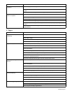
B. Generator Power
Trouble Remedy
No output at generator power ac
receptacles.
Reset circuit breakers (see Sections 6-1 and 6-2).
Check receptacle wiring and connections.
Check engine speed, and adjust if necessary (see Section 7-4 or 7-5). Output stops if engine speed is
too low.
Have Factory Authorized Service Agent check brushes, slip rings, capacitor C1, integrated rectifiers
SR1 and SR2, resistor R3 (Kohler only), and circuit board PC1.
High power output at generator power
ac receptacles.
Check engine speed, and adjust if necessary (see Section 7-4 or 7-5).
Move throttle lever to 50 Hz position for 50 Hz equipment (see Section 5-1 or 5-2).
Have Factory Authorized Service Agent check capacitor C1, resistor R3 (Kohler only), and circuit
board PC1.


