


. A complete Parts List is available at www.HobartWelders.com
OM-230 455 Page 12
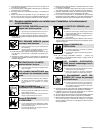
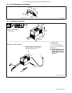
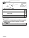
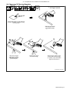
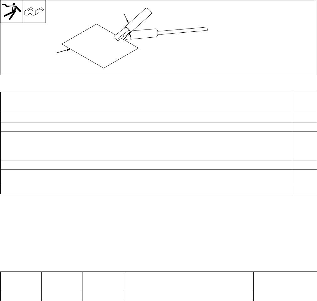
4-6. Connecting Work Clamp
. Do not connect work clamp to
the portion of the workpiece
that will fall when cut.
1 Work Clamp
2 Workpiece
Connect work clamp to a clean,
paint-free location on workpiece, as
close to cutting area as possible.
1
2
Ref 803 915-A
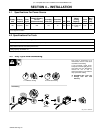
4-7. Electrical Service Guide For 120 VAC
50/60 Hz
Single
Phase
Input Voltage 120
Input Amperes At Rated Output 19
Max Recommended Standard Fuse Rating In Amperes
Circuit Breaker
1
, Time-Delay
2
20
Normal Operating
3
30
Min Input Conductor Size In AWG
4
12
Max Recommended Input Conductor Length In Feet (Meters)
34
(10)
Min Grounding Conductor Size In AWG
4
12
Reference: 2005 National Electrical Code (NEC) (including article 630)
1 Choose a circuit breaker with time-current curves comparable to a Time Delay Fuse.
2 “Time-Delay” fuses are UL class “RK5” .
3 “Normal Operating” (general purpose - no intentional delay) fuses are UL class “K5” (up to and including 60 amp), and UL class “H” ( 65 amp and
above).
4 Conductor data in this section specifies conductor size (excluding flexible cord or cable) between the panelboard and the equipment per NEC Table
310.16. If a flexible cord or cable is used, minimum conductor size may increase. See NEC Table 400.5(A) for flexible cord and cable requirements.
Y Caution: Failure to follow these fuse and circuit breaker recommendations could create an electric shock or fire hazard. These
recommendations are for a dedicated branch circuit that applies to the rated output and duty cycle of the power source.
4-8. Extension Cord Data
Input Voltage
Input Power
Phase
Hertz Conductor Size Max. Cord Length
120 V 1 50/60 12 AWG 50 ft (15 m)