


. A complete Parts List is available at www.HobartWelders.com
OM-230 455 Page 24
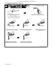
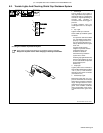
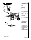
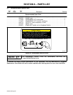
6-5. Torch And Work Cable Connections
Y Turn Off power source, and
disconnect input power.
If torch or work cable needs to be
removed or replaced, proceed as
follows:
1 Power Source
Remove wrapper from unit.
Torch Connections
Remove existing torch cable from
unit.
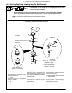
2 Strain Relief
3 Torch Cable
Insert strain relief on end of cable
through front panel opening. Slide
strain relief nut onto torch cable, but
do not tighten.
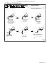
4 Air Line Connector
Install air line connector onto
compressor fitting.
5 Plug PLG4/Receptacle RC4
Connect PLG4 to receptacle RC4
on circuit board PC1.
6 Female And Male Friction
Terminal RC1/ELECTRODE
Connect female friction terminal
on end of black lead to
RC1/ELECTRODE.
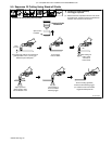
7 Female And Male Friction
Terminal RC2/TIP
Connect female friction terminal on
end of red lead to RC2/TIP.
Tighten strain relief nut.
Tighten strain relief around cable.
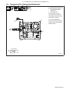
Work Cable Connections
Remove existing work cable from
unit.
8 Strain Relief
. Be sure to allow some work
cable slack inside the unit.
Insert strain relief on end of cable
through front panel opening. Slide
strain relief nut onto work cable and
secure strain relief to front panel.
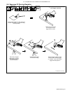
9 Work Lead Male Friction
Terminal
Connect work clamp lead to male
friction terminal labeled WORK on
circuit board PC1.
Reinstall wrapper.
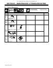
Tools Needed:
8
Ref. 804 852-B / 804 887-A
2
1
3
46
2
5/16 in
5
7
9
5
6 7