


OM-4418 Page 16
SECTION 5 − INSTALLATION
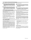
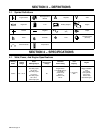
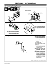
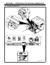
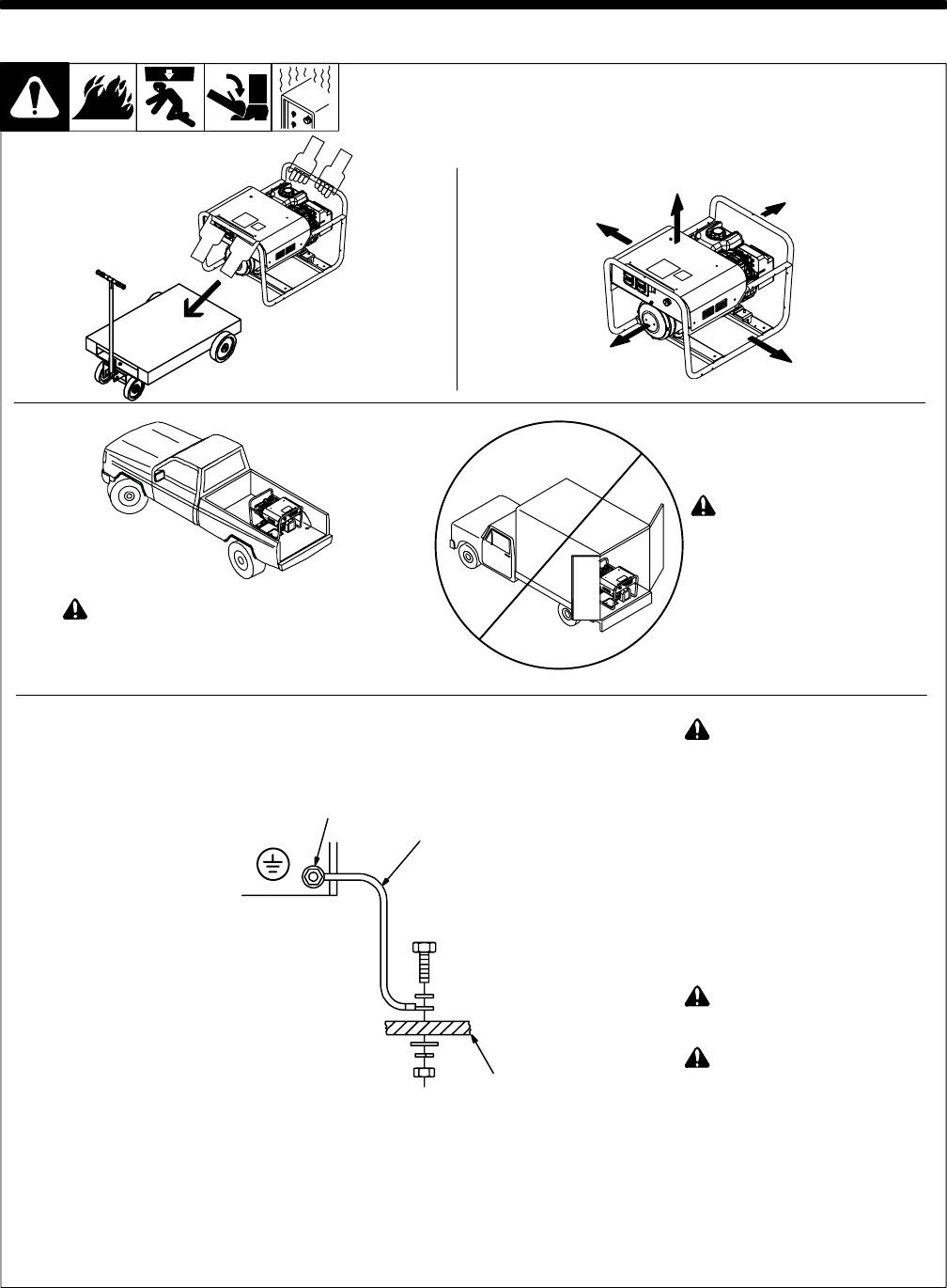
5-1. Installing Welding Generator
Ref install1 8/06 − Ref. 151 556 / 158 936-A / 803 467-C / S-0854
18 in
(460 mm)
18 in
(460 mm)
18 in
(460 mm)
18 in
(460 mm)
18 in
(460 mm)
Movement Airflow Clearance
Location
! Always securely fasten welding
generator onto transport vehicle
or trailer and comply with all
DOT and other applicable codes.
! Do not install unit where air
flow is restricted or engine
may overheat.
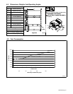
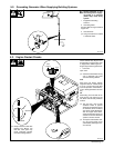
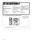
GND/PE
2
3
1
! Always ground generator
frame to vehicle frame to pre-
vent electric shock and static
electricity hazards.
1 Metal Vehicle Frame
2 Equipment Grounding
Terminal
3 Grounding Cable
Use #10 AWG or larger insulated
copper wire.
. Electrically bond generator
frame to vehicle frame by met-
al-to-metal contact.
! If unit does not have GFCI
receptacles, use GFCI-
protected extension cord.
! Bed liners, shipping skids,
and some running gear insu-
late the welding generator
from the vehicle frame. Al-
ways connect a ground wire
from the generator equip-
ment grounding terminal to
bare metal on the vehicle
frame as shown.
Grounding