


OM-945 Page 42
SECTION 12 − GENERATOR POWER GUIDELINES
. The views in this section are intended to be representative of all engine-driven welding generators. Your unit may differ from those shown.
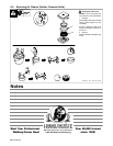
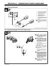
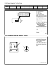
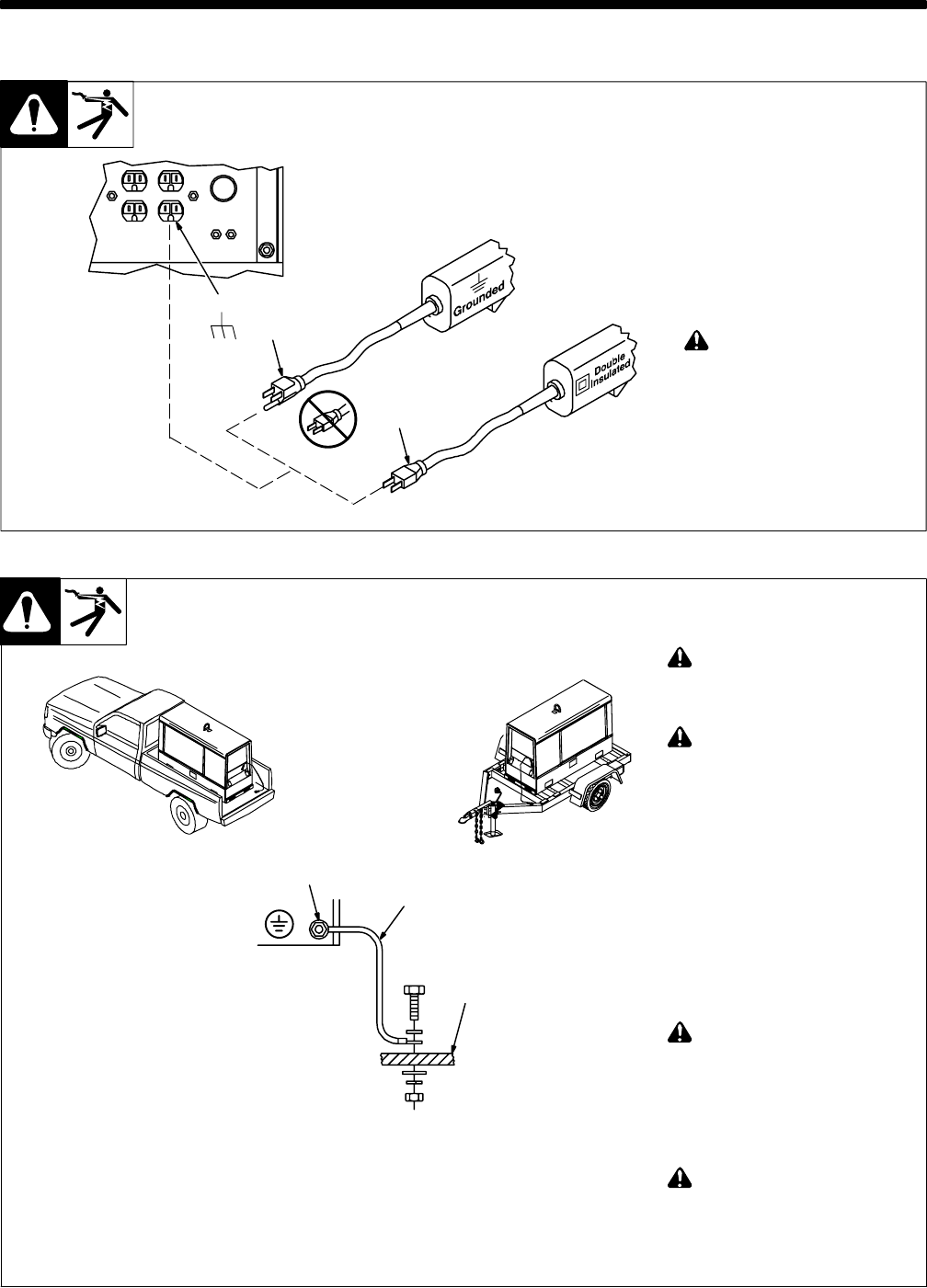
1 Generator Power Receptacles
− Neutral Bonded To Frame
2 3-Prong Plug From Case
Grounded Equipment
3 2-Prong Plug From Double
Insulated Equipment
. Be sure equipment has double
insulated symbol and/or word-
ing on it.
! Do not use 2-prong plug un-
less equipment is double in-
sulated.
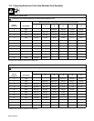
12-1. Selecting Equipment
gen_pwr 2007−04 − Ref. ST-159 730 / ST-800 577
OR
2
3
1
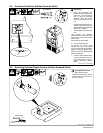
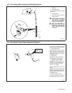
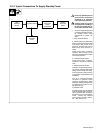
! Always ground generator
frame to vehicle frame to pre-
vent electric shock and static
electricity hazards.
! Also see AWS Safety & Health
Fact Sheet No. 29, Grounding
of Portable And Vehicle
Mounted Welding Generators.
1 Equipment Grounding Terminal
(On Front Panel)
2 Grounding Cable (Not Supplied)
3 Metal Vehicle Frame
Connect cable from equipment
ground terminal to metal vehicle
frame. Use #10 AWG or larger insu-
lated copper wire.
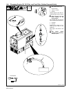
. Electrically bond generator frame
to vehicle frame by metal-to-met-
al contact.
! Bed liners, shipping skids, and
some running gear insulate the
welding generator from the ve-
hicle frame. Always connect a
ground wire from the genera-
tor equipment grounding ter-
minal to bare metal on the ve-
hicle frame as shown.
! If unit does not have GFCI re-
ceptacles, use GFCI-protected
extension cord.
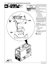
12-2. Grounding Generator To Truck Or Trailer Frame
S-0854
GND/PE
3
1
2