


OM-949 Page 13
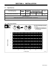
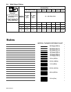
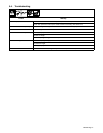
3-7. Electrical Service Guide
Input Voltage
230 V − 60 Hz
220 V − 50 Hz
Input Amperes At Rated Output 47.5
Max Recommended Standard Fuse Rating In Amperes
Circuit Breaker
1
, Time-Delay
2
50
Normal Operating
3
70
Min Input Conductor Size In AWG
4
12
Max Recommended Input Conductor Length In Feet (Meters) 87 (27)
Min Grounding Conductor Size In AWG
4
12
Reference: 2005 National Electrical Code (NEC) (including article 630)
1 Choose a circuit breaker with time-current curves comparable to a Time Delay Fuse.
2 “Time-Delay” fuses are UL class “RK5” .
3 “Normal Operating” (general purpose - no intentional delay) fuses are UL class “K5” (up to and including 60 amp), and UL class “H” ( 65 amp and
above).
4 Conductor data in this section specifies conductor size (excluding flexible cord or cable) between the panelboard and the equipment per NEC Table
310.16. If a flexible cord or cable is used, minimum conductor size may increase. See NEC Table 400.5(A) for flexible cord and cable requirements.
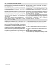
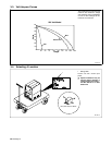
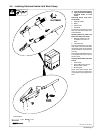
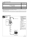
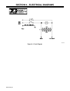
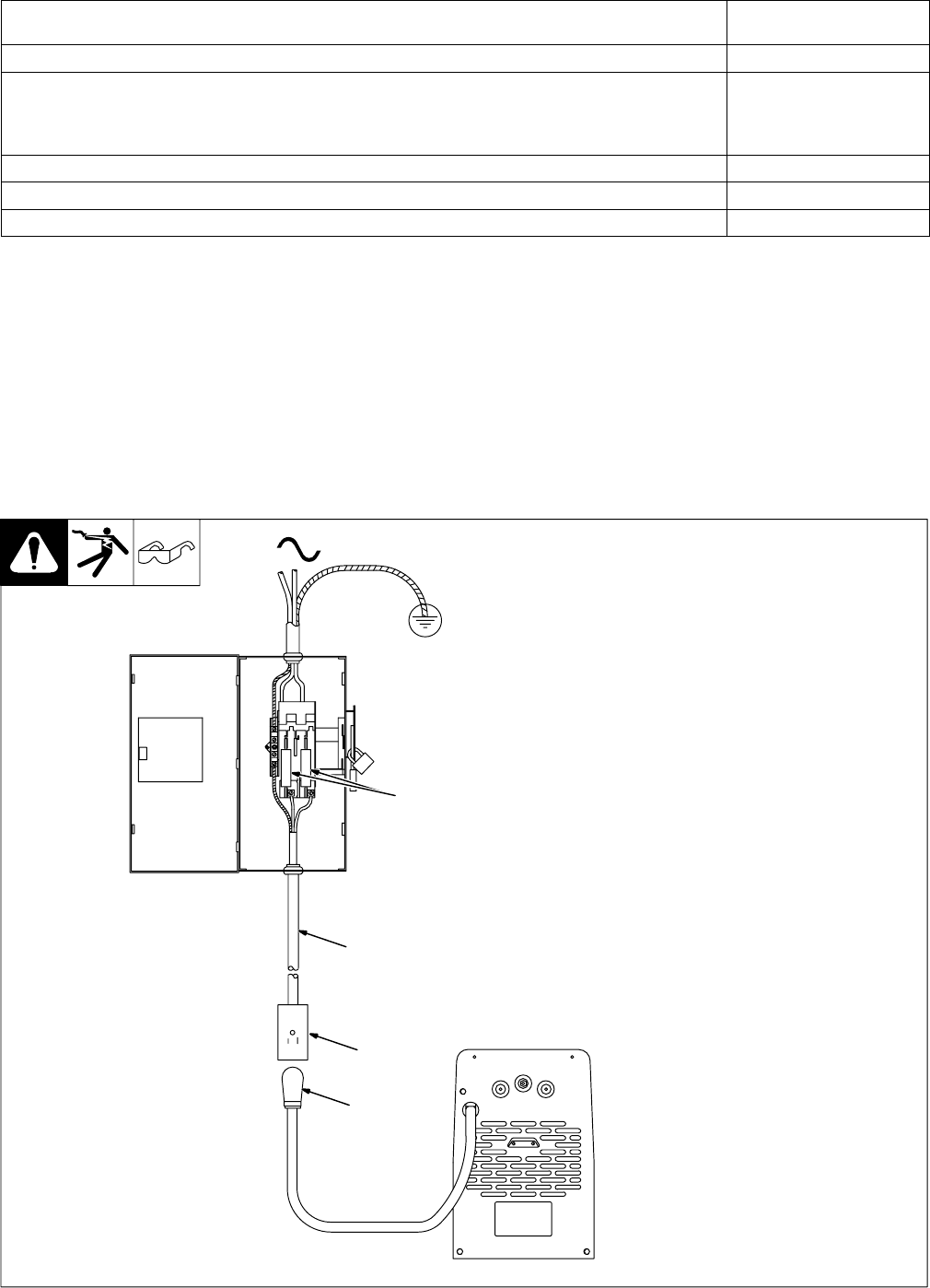
3-8. Connecting Input Power
Ref. 802 246-A
1
=GND/PE Earth Ground
4
1
3
2
Y Disconnect and lockout/tag-
out input power before instal-
ling receptacle.
Y Have only qualified persons
make this installation. See
rating label in Section 3-4, and
be sure to supply correct in-
put power.
1 Proper Receptacle
(NEMA 6-50R)
(User-Supplied)
Receptacle must comply with appli-
cable codes.
2 Input And Grounding
Conductors
See size and length using Section
3-7. Conductors must comply with
applicable codes.
3 Over-Current Protection
Select type and size of over-current
protection using Section 3-7.
4 Plug (NEMA 6-50P)
Connect plug to properly installed
receptacle.
Close and secure door on discon-
nect device. Remove lockout/tagout
device, and place switch in the On
position.