


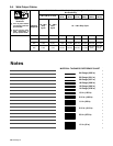
OM-949 Page 16
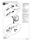
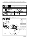
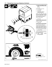
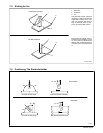
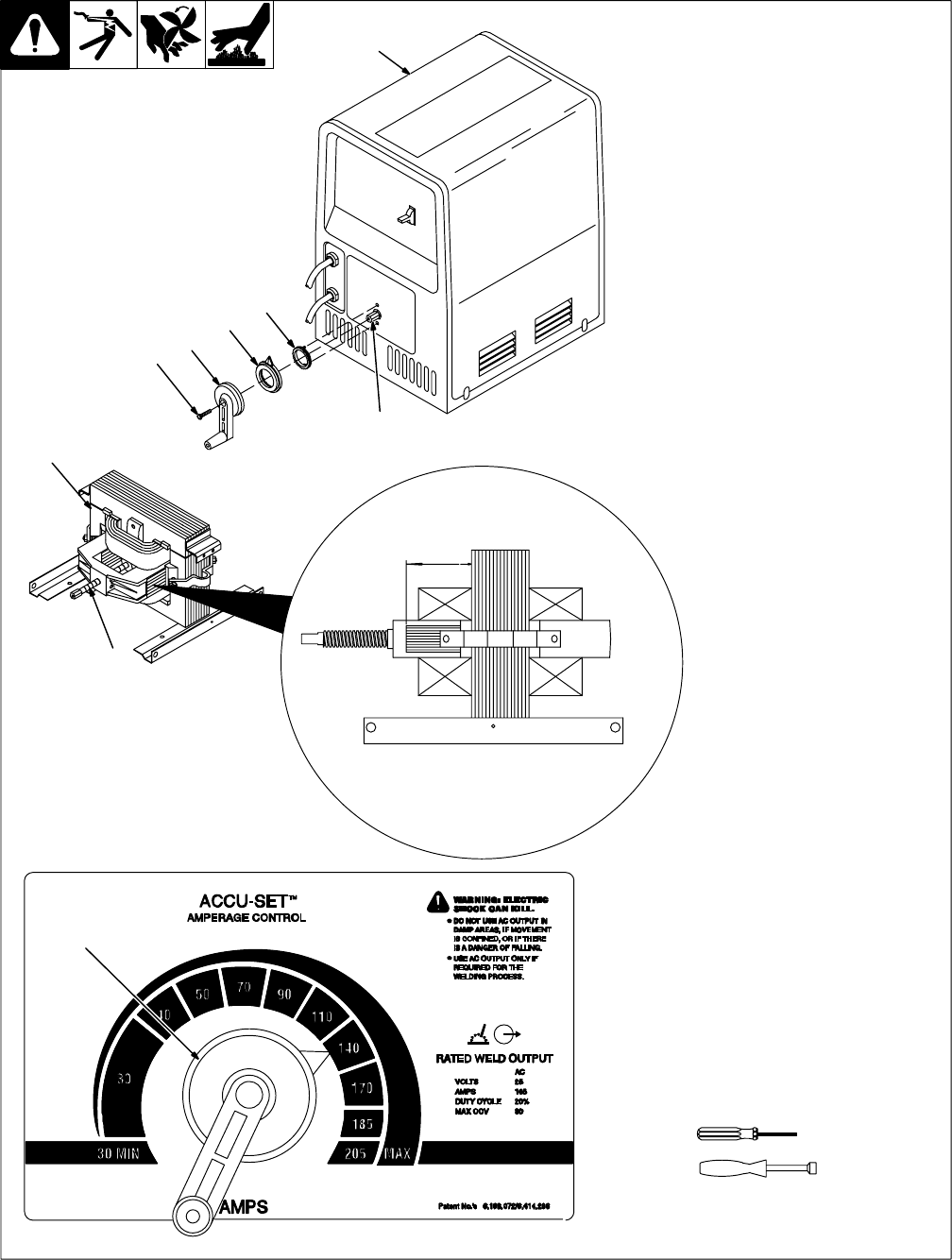
5-3. Reinstalling Amperage Adjustment Indicator
804 295-A / 803 564-B / 215 247-A
Y Turn Off welding power
source and disconnect input
power.
1 Wrapper
Remove wrapper from unit.
2 Crank Handle
3 Shunt Shaft
4 Transformer And Shunt
(Located Inside Unit)
Insert crank handle onto shunt
shaft protruding through front panel
and turn crank handle to adjust
shunt to 2-5/8 in (67 mm), (see de-
tail of transformer and shunt).
Remove crank handle.
5 Pinion Gear
Install pinion gear onto front panel
making sure anti-rotation pins are in
holes on front panel.
6 Pointer Gear
Install pointer gear overtop of pinion
gear and rotate so pointer is indicat-
ing 140 Amps (see example).
Install crank handle overtop the sta-
tor/pinion gear assembly with the
handle straight down. It may be
necessary to turn the handle slight-
ly so vertical alignment is possible.
7 Securing Screw
Install securing screw through han-
dle, into threaded hole in shunt
shaft. Tighten securely.
Y Install wrapper before
turning On power.
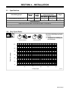
5/16, 3/8 in
4
3
Tools Needed:
2-5/8 in
(67 mm)
Viewed from right side of unit.
Proper alignment of pointer and crank handle.
T-20 Torx
2
1
2
5
6
3
7