


OM-278 Page 19
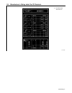
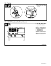
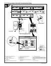
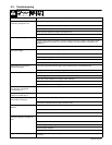
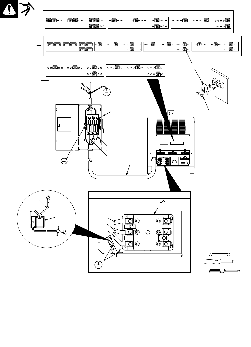
3-12. Placing Jumper Links And Connecting Input Power
1
230 VOLTS
Ref. S-174 973-A
575 VOLTS460 VOLTS
ST-800 103-B / Ref. ST-801 116
Check input voltage available at site.
1 Jumper Link Label
Check label – only one is on unit.
2 Jumper Links
Move jumper links to match input voltage.
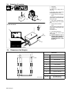
3 Input And Grounding Conductors
See Section 3-11.
4 Line Disconnect Device
See Section 3-11.
5 Reed Switch (Ground Current Sensor)
(Optional)
6 Grounding Conductor
If unit is equipped with optional ground current
sensor, route grounding conductor through
reed switch two times and connect to ground
terminal.
Close access door.
3/8 in
3/8 in
IMPORTANT
GND/
3
PE
Connect GND/PE
Conductor First.
Input Contactor
L1 (U)
L2 (V)
L3 (W)
GND/PE
Earth Ground
L1 (U)
L2 (V)
L3 (W)
3
4
Tools Needed:
5
6
2
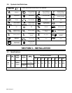
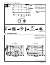
380 VOLTS 400 VOLTS 440 VOLTS
Ref. S-174 975-A
220 VOLTS
(FACTORY OPTION)
Do not overtighten
jumper link nuts.
Connect GND/PE
Conductor First.
380 VOLTS 520 VOLTS