


22 Sp
Pistola Pulverizadora Multiuso
Mantenimiento
(Continuación)
5. Sáquele las tuercas que sostienen los
empaques y reemplácelos SOLO si no
puede eliminar la fuga de material
después de apretar las tuercas. No
apriete demasiado estas tuercas ya
que podría restringir el movimiento
de la aguja.
6. Ensamble las piezas en orden
contrario a lo anterior y use aceite sin
silicón en las piezas movibles.
Aplíquele Vaselina o grasa liviana a
las conexiones con roscas y a las de
las mangueras.
a cardboard target. Be sure the spray
material is clean and free from lumps.
3. Fill the canister about 3/4 full with
material and start the air
compressor. Be sure the hose(s) is
long enough to allow a full
movement of the gun across the
surface to be painted.
4. Be sure that the air pressure
regulator is set for the proper
operation of the gun. Refer to the
specifications section. Air pressure
should be checked at the spray gun
inlet with the trigger pulled.
5. Set up a piece of cardboard or other
scrap material to use as a target and
adjust for best spray pattern.
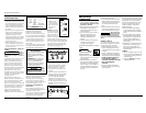
MATERIAL & PATTERN
ADJUSTMENTS
Always test spray
gun on scrap
material to avoid damage to workpiece.
The fluid control knob will control
trigger travel and the amount of
material flowing through the gun.
(Turn the knob clockwise to reduce
flow, counterclockwise to increase the
flow.) This adjustment depends, in
part, on the amount of air flowing
through the gun. Air flow can be
adjusted only at the compressor’s
pressure regulator. Spray test patterns
on scrap cardboard with gun 8” away
from surface. Trigger short, one second
bursts and make adjustments with this
knob until the pattern is the desired
oval shape and the material is evenly
distributed on the surface with no
heavy or thin spots. The pattern should
feather out at the edges (See Figure 5).
NOTE: If there is sagging, too much
material is being applied. If there is an
“orange peel” effect, the material is
too thick.
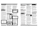
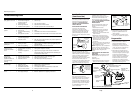
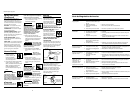
NOTICE
NON-BLEEDER TO BLEEDER
CONVERSION
IMPORTANT: Spray guns are shipped
for non-bleeder operation.
(See Figure 4)
1. Remove fluid control knob, large
spring and fluid needle.
2. Remove and retain small spring or
place inside large spring to store.
3. Reassemble unit by reversing step 1.
Preparation
MATERIAL PREPARATION
1. Before using desired material in the
spray gun, spray a compatible
thinner or solvent through the gun
to remove any contaminants and
residue.
2. Thoroughly mix the material in
accordance with the manufacturer’s
instructions. If necessary, thin per
paint manufacturer’s instructions.
Strain material through a paint
strainer. Test the consistency of the
material by making a few strokes on
3
Set Up (Continued)
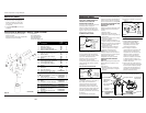
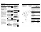
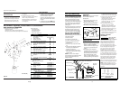
USING A PRESSURIZED PAINT TANK
This model is readily adaptable for use
with a pressurized paint tank. This
allows continuous spraying of large
quantities of paint without stopping. It
also allows the gun to be used while
being held in ANY position without
spilling paint.
The proper connections to make when
using a pressurized paint tank are as
illustrated in Figure 3. Refer to the
instructions supplied with the paint
tank for connections and usage. DO
NOT USE A PAINT TANK WITHOUT
READING THOSE INSTRUCTIONS.
Prepare the spray gun for use with the
paint tank as follows:
1. Remove canister.
2. Unscrew the material tube.
3. Unscrew canister top and O-ring.
4. Remove setscrew from hole in
canister cover.
5. Remove air cap to expose the fluid
tip.
6. Locate the small tapped hole below
the fluid tip and assemble the
setscrew into this hole.
7. Fasten the material hose from the
paint tank to the gun body in place
of the canister.
NOTE: Be sure to use the adapter
when attaching the material hose (See
Figure 10, item 26 for fluid hose
adapter location).
Figure 3 - Paint Tank
Connections
Paint Tank Regulator
Safety Valve
Air Hose
Paint Tank
Material Hose
Air Hose
High - Out To Spray Gun
High - In from
compressor
Air Source
Regulator
Fluid
Control
Knob
Fluid Needle
Large Spring
Small Spring
Figure 4
Correct Paint Too
Thick
Paint
Too Thin
Figure 5 - Pattern Consistency
(Atomization)
PARA ALMACENAR
1. Cuando no vaya a usar la pistola
pulverizadora, gire la perilla de
control de fluído en sentido
contrario a las agujas del reloj para
reducir la tensión del resorte sobre
la aguja.
2. La pistola pulverizadora DEBEestar
bien limpia y ligeramente lubricada.
Para ordenar repuestos, sírvase llamar al concesionario
más cercan a su domicilio
Puede escribirnos a:
The Campbell Group
Attn: Parts Department
100 Production Drive
Harrison, OH 45030 U.S.A.
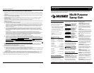
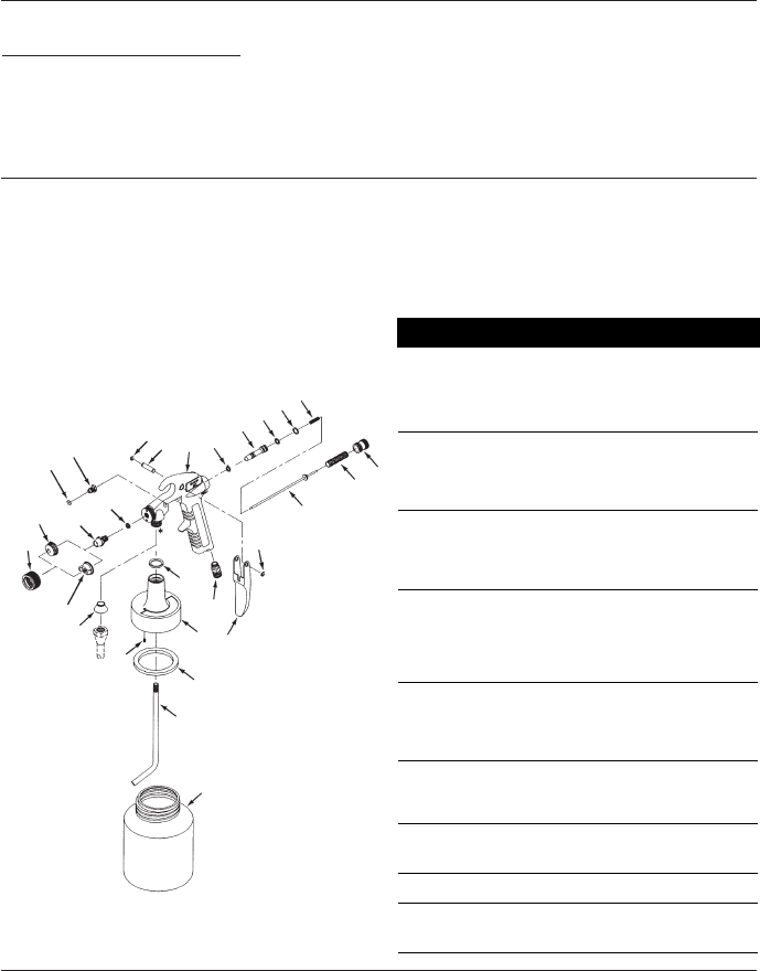
1 Ensamblaje del cuerpo
de la pistola No disponible 1
2 Anillo retenedor ■ 2
3 Pasador del gatillo ■ 1
4 Ensamblaje de la aguja de flujo ● 1
5 Anillo de la tapa de aire ▲ 1
6 Tapa de aire (mezcla externa) ▲ 1
7 Tapa de aire (mezcla interna) ▲ 1
8 Boquilla ● 1
9 Anillo en O de 8,7mm x 5,6mm ■ 2
10 Resorte ● 1
11 Perilla para el control del material ● 1
12 Pistón de la válvula ● 1
13 Anillo en O de 10mm x 6,4mm ■ 1
14 Anillo en O de 11mm x 8mm ■ 1
15 Resorte ● 1
16 Anillo en O de 17mm x 22mm ■ 1
17 Empaque (●) (■)1
juego
18 Tuerca para sostener el empaque ● 1
19 Ensamblaje DH404200AV 1
20 Tornillo de cabeza tubular
de 5-40 x 3,2mm ● 1
21 ■ Empaque para el envase
(paquete de 3) DH420400AV 1
22 Tubo de material DH065700AV 1
23 Conexión de 6,4mm NPS (M)
para la manguera HF001800AV 1
24 Gatillo DH011800AV 1
25 Envase DH054001AV 1
26 Adaptador para la
manguera de flujo DH006900AV 1
(◆) Llave tipo Allen de 1,6mm ST010900AV 1
JUEGOS DE REPUESTOS DISPONIBLES
PARA LA REPARACIÓN Y MANTENIMIENTO
■ Empaques DH420100AV
● Control de flujo DH420200AV
▲ Control de patrón DH420300AV
(◆) No se muestra
No. de Número del
Ref. Descripción Repuesto Ctd
* 3/8 NPS (M)
1
2
3
4
5
6
7
8
9
10
11
12
13
14
15
16
17
18
19
20
21
22
23
24
25
26
9
Sirvase darnos la siguiente información:
- Número del modelo
- Número de Serie o código con fecha (de haberlo)
- Descripción y número del repuesto según la lista de repuestos
Figura 10