


21
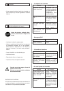
• On receiving the machine check its condition.
• Always keep it perfectly clean
• Check the supply cable and the extension lead per-
iodically
• Always keep alert when working
• Check that the parts are properly fixed (no abnormal
vibration) and that it is correctly assembled.
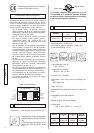
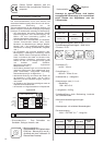
3 Inspection - Description of the machine
Chassis
1
Disc casing
12
Rail
13
Plate
14
Plate stops
15
Angled cutting guide
18
Plate side extension
19
Leg
2
Leg locking knob
3
Water pump
4
locking Clip
5
90° to 45° locking knob
6
13 mm spanner
7
Drain plug
8
Motor
9
Lack of voltage switch
10
Operating handle
11
English
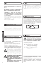
For these different operations always
disconnect the machine
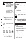
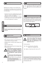
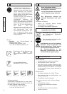
4 Handling and Transport
ASSEMBLING THE LEGS
– Slacken the knob (H). Take out the legs fixed under-
neath the frame [
SEE FIG. 3]
– Lift up the back of the machine and slide the two rear
legs into place. Tighten the knobs (3) [
SEE FIG. 1]
– Do the same with the front legs.
TRANSPORT
– Lock the cutting head to the rear of the machine by
means of the clip (A) - [
SEE FIG. 2].
– Remove the legs in the reverse order to the assem-
bly (first the front, then the back). Store them under
the machine, remembering to fix them by tightening
knob H [
SEE FIG. 3].
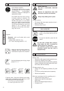
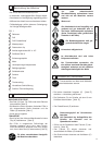
The working area must be complete-
ly cleared, well lit and all safety
hazards removed (no water or dan-
gerous objects in the vicinity)
Motor off.
The operator must wear protec-
tive clothing appropriate to the
work he is doing. We recom-
mend that this includes both
eye and ear protection
Any persons not involved in the work
should leave the working area
Use only blades marked with a maxi-
mum operating speed greater than
blade shaft speed
Please read the instructions for use
prior to operating the machine for
the first time.
The use of ear protection is manda-
tory.
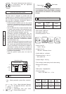
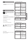
5 Check before starting
6 Fitting the disc
Disconnect the machine by unplugging
the supply cable.
• Release the two knobs (C) - [SEE FIG. 4], remo-
ve them and then remove the guard.
• Unscrew the disk clamping nut (D)- [
SEE FIG. 5]
using a 13 mm spanner.
• Remove the clamping plate (E) and fit the disk.
• Check the disk position on the centring plate (F) -
[
SEE FIG. 6]
• Refit the clamping plate (E) and tighten the nut
(D).
• Replace the guard, tighten the knobs (C).
Take care about the direction of rota-
tion which is shown by an arrow on
one of the faces.
Make sure the contact faces of
flanges, of blade and the axle are
clean.
FIG. 1