


Page 9
Testing the Resistance Function
To verify the accuracy of the resistance function, do the following:
1. Connect the calibrator to VΩ and COM on the meter.
2. Turn the rotary switch to Ω.
3. Apply the inputs for step 1-4 in Table 3.
4. Compare the meter display readings to the display readings in Table 3.
5. If the display reading falls outside of the range shown in Table 3, the meter does not meet specification.
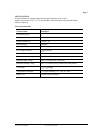
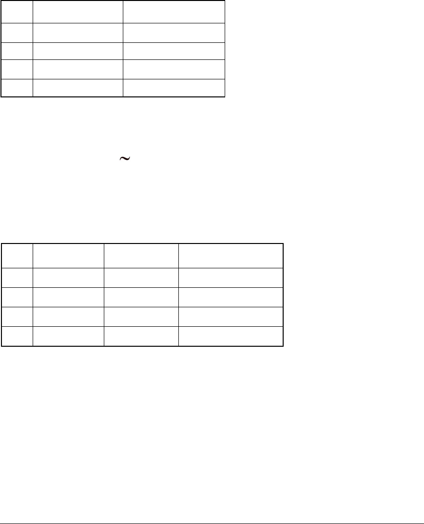
Table 3 Resistance Test:
Step Source Reading
1 100 Ω 97 to 103
2 180 Ω 176 to 184
3 1000 Ω 988 to 1012
4 1800 Ω 1780 to 1820
Max. Open Circuit Voltage: 3V
Continuity check: Beeper sounds if the resistance of the circuit under test is less than 25 Ω. It will then
turn off if the resistance is increased beyond 400 Ω.
Amp (A) Function
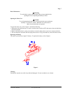
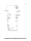
1. Turn the rotary switch to A
position.
2. Refer to Figure 1 and disconnect probes from probe test points.
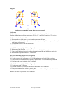
3. Place the conductor anywhere within the sensor zone as shown in the shaded areas of Figure 2.
4. Apply the inputs for steps 1 - 4 in Table 4.
5. For each input, compare the reading on the meter display to the reading in Table 4.
6. If the display reading falls outside of the range shown in Table 4, the meter does not meet specification.
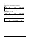
Table 4 ACA Test:
Step Source Frequency Reading
1 19.0A 50Hz 18.1 to 19.9
2 19.0A 500Hz 18.1 to 19.9
3 190.0A 50Hz 184.0 to 196.0
4 190.0A 500Hz 184.0 to 196.0
Form number TM61095 Rev 2 September 2002