


12
English
LUBRICATION
Low viscosity grease is applied to this rotary hammer
so that it can be used for a long period without replacing
the grease. Please contact the nearest authorized service
center for grease replacement when any grease is
leaking from a loosened screw.
Further use of the rotary hammer with incorrect grease
will cause the machine inefficiency and reduce the
service life.
CAUTION:
A special grease is used with this machine, therefore,
the normal performance of the machine may be badly
affected by use of other grease. Please be sure to let
one of our authorized service center undertaking
replacement of the grease.
MAINTENANCE AND INSPECTION
1. Inspecting the drill bits
Since use of a dull tool will cause motor
malfunctioning and degraded efficiency, replace the
drill bit with new ones or resharpen them without
delay when abrasion is noted.
2. Inspecting the mounting screws
Regularly inspect all mounting screws and ensure
that they are properly tightened. Should any of the
screws be loose, retighten them immediately. Failure
to do so could result in serious hazard.
3. Maintenance of the motor
The motor unit winding is the very “heart” of the
power tool. Exercise due care to ensure the winding
does not become damaged and/or wet with oil or
water.
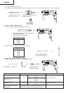
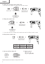
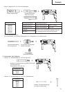
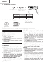
4. Inspecting the carbon brushes (Fig. 21)
The motor employs carbon brushes which are
consumable parts. When they become worn to or
near “wear limit”, it could result in motor trouble.
When an auto-stop carbon brush is equipped, the
motor will stop automatically.
At that time, replace both carbon brushes with new
ones which have the same carbon brush numbers
shown in Fig. 21.
In addition, always keep carbon brushes clean and
ensure that they slide freely within the brush holders.
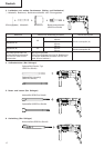
5. Replacing a carbon brush (Fig. 22)
⅜ Disassembling
(1) Loosen the three screws on the handle cover, and
remove the handle cover.
(2) Lift out the brush holder together with the carbon
brush, while being very careful not to forcibly pull
the lead wires within the brush holder.
(3) Withdraw the brush terminal, and remove the carbon
brush from the brush holder.
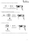
⅜ Reassembling
(1) Place a new carbon brush into the brush holder,
and connect the brush terminal to the carbon brush.
(2) Return the brush holder and other parts to their
original positions, as illustrated in Fig. 22.
(3) Place the lead wire in the specified position. Be very
careful not to allow the lead wire to contact the
armature or rotating parts of the motor.
(4) Mount the handle cover, while being careful to
ensure it does not pinch the lead wire, and secure
it firmly with the three screws.
CAUTION:
Should the lead wire be pinched by the handle
cover or come in contact with the armature or
rotating parts of the motor, a serious danger of
electric shock to the operator will be created.
Excercise extreme caution in disassembling and
reassembling the motor, following the above
procedures exactly.
Do not attempt to disassemble any parts other than
those necessary to effect replacement of the carbon
brush.
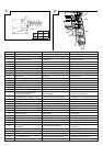
6. Service parts list
A: Item No.
B: Code No.
C: No. Used
D: Remarks
CAUTION:
Repair, modification and inspection of Hitachi Power
Tools must be carried out by an Hitachi Authorized
Service Center.
This Parts List will be helpful if presented with the
tool to the Hitachi Authorized Service Center when
requesting repair or other maintenance.
In the operation and maintenance of power tools,
the safety regulations and standards prescribed in
each country must be observed.
MODIFICATIONS:
Hitachi Power Tools are constantly being improved
and modified to incorporate the latest technological
advancements.
Accordingly, some parts (i.e. code numbers and/or
design) may be changed without prior notice.
NOTE:
Due to HITACHI’s continuing program of research and
development, the specifications herein are subject to
change without prior notice.
IMPORTANT:
Correct connection of the plug
The wires of the mains lead are coloured in accordance
with the following code:
Blue: Neutral
Brown: Live
As the colours of the wires in the mains lead of this
tool may not correspond with the coloured markings
identifying the terminals in your plug proceed as follows:
The wire coloured blue must be connected to the
terminal marked with the letter N or coloured black.
The wire coloured brown must be connected to the
terminal marked with the letter L or coloured red.
Neither core must be connected to the earth terminal.
NOTE:
This requirement is provided according to BRITISH
STANDARD 2769: 1984.
Therefore, the letter code and colour code may not be
applicable to other markets except The United Kingdom.