


English
5
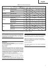
Voltage (by areas)* (110V, 115V, 120V, 127V, 220V, 230V, 240V)
Power Input 400 W*
Max. cutting depth Wood: 65 mm
Mild steel: 6 mm
No-load speed 0 ∼ 3000 min
–1
Stroke 18 mm
Min. cutting radius 25 mm
Weight (without cord) 1.6 kg
4. Dust produced in operation
The dust produced in normal operation may affect
the operator’s health. Either of following way is
recommended.
a) Wear a dust mask
b) Use external dust collection equipment
When using the external dust collection equipment,
connect the adapter with the hose from external dust
collection equipment.
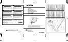
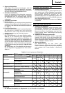
MOUNTING THE BLADE
1. Use the accessory hexagonal bar wrench to loosen
the blade set screws on the set ring, as shown in Fig. 1.
2. Holding the blade with its cutting edge facing the
front, insert the mounting portion of the blade into
the plunger groove until it touches the bottom of the
groove.
3. As shown in Fig. 1, firmly clamp the side scerw.
CAUTION
⅜ Loosened set screws may cause the blade to be
damaged. Always ensure that the set screws are
securely tightened. Always ensure that the plunger
groove is clean and clear of sawdust to ensure proper
blade mounting and set screw clamping.
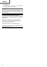
CHIP COVER POSITIONING
1. Chip cover
Use the chip cover to reduce flying of cut particles
and to easily operate the saw.
Slide the chip cover while lightly pressing its front
section.
The chip cover can be set at three positions as shown
in Fig. 2.
2. How to choose the position of the chip cover
Set the chip cover to the first step when attaching or
removing the blade.
Set the chip cover to the second step when cutting
wooden materials.
Set the chip cover to the second or third step when
cutting metal materials such as steel.
CAUTION
⅜ Keep always the chip cover in the low position when
operating the tool.
⅜ Wear protection glasses even if the chip cover is
used.
SPECIFICATIONS
* Be sure to check the nameplate on product as its subject to change by areas.
STANDARD ACCESSORIES
(1) Blade No. 41................................................................ 1
For cutting thick lumber
(2) Splinter guard ............................................................. 1
(3) Chip cover ................................................................... 1
(4) Hexagonal bar wrench ............................................... 1
Standard accessories are subject to change without
notice.
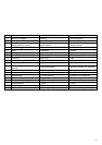
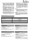
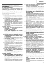
OPTIONAL ACCESSORIES (sold separately)
(1) Blades No. 11, No. 12, No. 15, No. 16, No. 21,
No. 22, No. 41*
Refer to Table 1 for use of the blades.
* No. 41 Blade is a standard accessory.
(2) Guide
(3) Dust collector
Optional accessories are subject to change without notice.
APPLICATIONS
⅜ Cutting various lumber and pocket cutting.
⅜ Cutting mild steel plate, aluminum plate, and copper
plate.
⅜ Cutting synthetic resins, such as phenol resin and
vinyl chloride.
⅜ Cutting thin and soft construction materials.
PRIOR TO OPERATION
1. Power source
Ensure that the power source to be utilized conforms
to the power requirements specified on the product
nameplate.
2. Power switch
Ensure that the power switch is in the OFF position. If
the plug is connected to a receptacle while the power
switch is in the ON position, the power tool will start
operating immediately, which could cause a serious
accident.
3. Extension cord
When the work area is removed from the power
source, use an extension cord of sufficient thickness
and rated capacity. The extension cord should be
kept as short as practicable.