


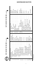

6
MAINTENANCE SECTION
Always wear eye protection when operating or
performing maintenance on this tool.
Always turn off air supply and disconnect air supply
hose before installing, removing or adjusting any
acce ssory on this tool, or before performing any
maintenance on this tool. Failure to do so could r esult
in injury.
LUBRICATION
Each time a Model 132 Air Hammer is disassembled for
maintenance, repair or replacement of parts, lubricate the
tool as follows:
Inject several drops of Ingersoll--Rand No. 10 Oil
into the air inlet and operate the tool for 5 seconds to
coat the internal parts with oil.
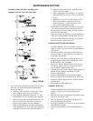
DISASSEMBLY
General Instructions
1. Do not disassemble the tool any further than
nece ssary to replace or repair damaged parts.
2. Whenever grasping a tool or part in a vise, always use
leather--covered or copper--covered vise jaws to
protect the surface of the part and help prevent
distortion. This is particularly true of threaded
members and housings.
3. Do not remove any part which is a press fit in or on a
subassembly unless the removal of that part is
necessary for repairs or replacement.
4. Do not disassemble the tool unless you have a
complete set of new gaskets and O--rings for
replacement.
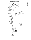
Disassembly of the Tool
1. Clamp the Handle (1) in leather--covered or
copper--covered vise jaws with the accessory end
upward.
2. Remove the Tool Retainer (25 or 25A) and any
accessory from the Barrel (24).
3. Remove the Exhaust Deflector (22) from the Barrel.
4. Remove the Locking Key (21) that keeps the Barrel
from unscrewing from the Handle Assembl y.
5. Carefully unscrew the Barrel from the Handle
Assembly.
6. Remove the Piston (23) and the Valve Box Assembly.
Disassembly of the Throttle Mechanism
1. Clamp the Handle in leather--covered or
copper--covered vise jaws with the Air Inlet Bushing
(17) upward.
2. Remove the Throttle Adjuster Body (10).
3. Unscrew the Throttle Adjuster Cap Screw (16) and
remove the Throttle Adjuster Knob (14), Throttle
Adjuster Stop Ball (13), Throttle Adjuster Stop Spring
(12), and the Throttle Adjuster Sleeve (15).
4. Remove the Throttle Adjuster Screw (11), the Throttle
Valve Spring (9), and the Throttle Valve Assembly (5)
from the Handle.
5. Remove the Air Inlet Bushing.
6. Rotate the Handle in the vise to gain access to the
Intermediate Lever Pin (4). Drive out the Pin.
7. Carefully remove the Trigger (2) and the Intermediate
Leve r (3).
Disassembly of the Valve Box Assembly
1. Separate the two halves of the Valve Box Assembly.
A small brass or plastic hammer may be needed to
gently tap the Valve Box (18) apart.
2. Carefully remove the Dowel Pin (19) and the Valve
(20).
ASSEMBLY
General Instructions
1. Whenever grasping a tool or part in a vise, always use
leather--covered or copper--covered vise jaws. Take
extra car e with threaded parts and housings.
2. Always clean every part and wipe every part with a
thin film of oil before installation.
3. Apply a film of O--ring lubricant to all O--rings before
final assembly.