


7
MAINTENANCE SECTION
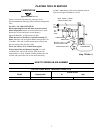
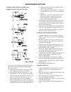
Assembly of the Valve Box Assembly and
Lapping Oversize Valve into Valve Box
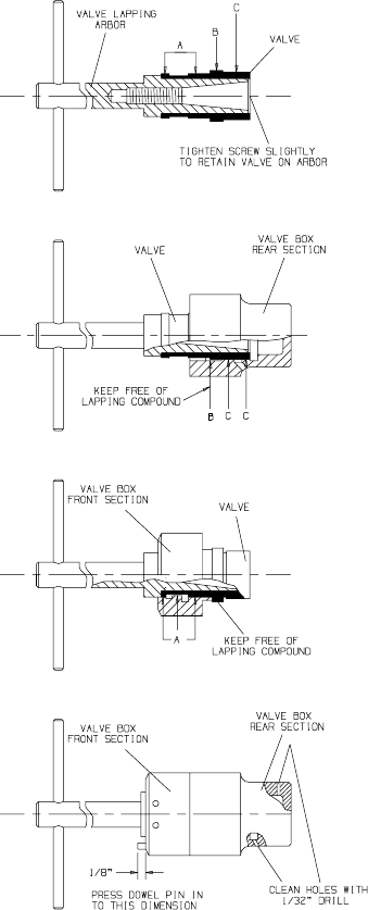
Figure 1
Figure 2
Figure 3
Figure 4
(Dwg. TPB130)
1. An oversize Valve (20) must be lapped into the Valve
Box (18). Use Grade 320 lapping compound and
proceed as follows:
a. Install the Valve on the No. 29189 or No. 29407
Valve Lapping Arbor as shown in Figure 1.
b. Apply lapping compound to diameter “C” only;
keep diameter “B” free of compound at all times.
Insert the compound--coated end of the Va lve into
the rear secti on of the Valve Box as shown in
Figure 2 and lap until a free fit is obtained.
c. Wipe all compound from the Valve and from the
internal diameter “B” in the Valve Box. Allow the
compound to remain on the internal diameter “C”.
d. Install the front section of the Valve Box on the
Arbor as shown in Figure 3.
e. Apply compound to Valve diame ter “A” and lap
the small end of the valve to a free fit in the front
section.
f. Slide the rear section of the Valve Box over the
Valve and assemble it on the front section as
shown in Figure 4. Lap the Valve until it fits
freel y in the assembled Valve Box.
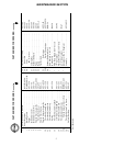
2. Disassemble the Valve Box, clean the air ports with a
1/32” drill and wash the Valve and both sections of
the Valve Box in a clean, suitable solution to remove
all trace of the compound.
3. Apply 6 or 8 drops of light oil to the external surface
of the Valve and assemble it with the Dowel Pin (19)
in the Valve Box. Shake the assembly to see that the
Valve moves freely in the Valve Box.
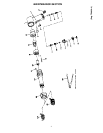
Assembly of the Throttle Mechanism
1. Clamp the Handle of the tool in leather--covered or
copper--covered vise jaws with the Air Inlet Bushing
(17) upward.
2. With a new Throttle Valve Seal (6) on the Throttle
Valve Assembly (5), place the Valve Assembly into
the Handle, Seal upward.
3. With the stem of the Throttle Adjusting Screw (11)
going through the Throttle Valve Spring (9), install
the Spring/Screw into the Handle.
4. With a new Throttle Adjuster Sleeve Seal (15A) on
the Throttle Adjuster Sleeve (15), place the Sleeve
into the Throttle Adjuster Body (10).
5. Carefully place the Throttle Adjuster Stop Spring (12)
and the Throttle Adjuster Stop Ball (13) in the
Throttle Adjuster Body.
6. Secure the Spring/Ball with the Throttle Adjuster
Knob (14) and the Throttle Adjuster Cap Screw (16).
7. Secure the Throttle Adjuster Screw with the Throttle
Adjuster Body.
8. Reinstall the Air Inlet Bushing (17).
Assembly of the Tool
1. Clamp the Handle of the tool in leather--covered or
copper--covered vise jaws with the barrel bore
upward.
2. Place the Valve Box Assembly into the Handle, larger
half of the Valve Box in first.
3. With the Piston (23) in the bore of the Barrel (24),
screw the Barrel into the Handle.
4. Place the Locking Key (21) into one of the slots in the
Barrel/Handle Assembly.
5. Secure the Locking Key with the Exhaust Deflector
(22).