


Always wear eye protection when operating or
performing maintenance on this tool.
Always turn off the air supply and disconnect the air
supply hose before installing, removing or adjusting any
accessory on this tool, or before performing any
maintenance on this tool.
LUBRICATION
Each time a Series 2906P Impactool is disassembled for
maintenance and repair or replacement of parts, lubricate
the tool as follows:
1. Work approximately 6 to 8 cc of Ingersoll–Rand
No. 105 Grease into the impact mechanism. Coat the
Anvil (48 or 100) lightly with grease around the
Hammer Case Bushing (45). Inject approximately 1 to
2 cc of grease into the Grease Fitting (25).
2. Use Ingersoll–Rand No. 10 Oil for lubricating the
motor. Inject approximately 1 to 2 cc of oil into the air
inlet before attaching the air hose. Remove the Oil
Chamber Plug (4) and fill the oil chamber.
DISASSEMBLY
General Instructions
1. Do not disassemble the tool any further than necessary
to replace or repair damaged parts.
2. Whenever grasping a tool or part in a vise, always use
leather–covered or copper–covered vise jaws to protect
the surface of the part and help prevent distortion. This
is particularly true of threaded members and housings.
3. Do not remove any part which is a press fit in or on a
subassembly unless the removal of that part is
necessary for repairs or replacement.
4. Do not disassemble the tool unless you have a
complete set of new gaskets and O–rings for
replacement.
Disassembly of the Impactool
1. Clamp handle of Impactool in a vise with square drive
pward.
2. Unscrew and remove the four Hammer Case Cap
Screws (47).
3. While lightly tapping on end of Anvil (48 or 100) with
a plastic hammer, lift off the Hammer Case
Assembly (44).
4. Grasp Hammer Frame (41) and carefully lift off entire
impact mechanism, making certain not to drop the two
Hammer Pins (42).
5. Lift Hammer Frame Washer (43) off Motor Housing
(1) and remove Impactool from vise.
Disassembly of the Impact Mechanism
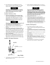
1. Set mechanism, driver end up, on a workbench.
Note the twin hammers within the Hammer Frame.
These are identical, but must be placed in the
Hammer Frame in a certain relationship. Using a
felt–tipped pen, mark the top hammer “T ” and
the bottom hammer “B ” with the arrows pointing
upward. Mark both Hammers on the same end.
2. With mechanism sitting upright on a workbench,
slowly rotate Anvil in a clockwise direction until it
comes up solid.
If you continue to rotate the Anvil, it will cam the
Hammers out of engagement. Do not allow this to
happen; merely rotate the Anvil until it comes up
solid.
3. Hold Hammer Frame firmly and, without disturbing
hammers, gently lift Anvil, simultaneously rotating it
clockwise about 1/8 of a turn, from the Hammer
Frame.
The twin hammers will be free to slide from the
Hammer Frame when the Hammer Pins are
removed. Do not drop the Hammers.
4. With Anvil removed, lift out the two Hammer Pins.
5. Remove the Hammers.
Disassembly of the Reverse Valve
1. Unscrew Reverse Valve Knob Screw (24) and remove
Reverse Valve Knob (23).
This Screw is installed with a thread locking
compound.
2. While slowly rotating Reverse Valve (20), withdraw it
from Reverse Valve Bushing (18).
Be careful not to lose the Reverse Valve Detent Ball
(21) and Spring (22) from the hole in the side of the
Reverse Valve.
3. Remove the two Reverse Valve Bushing Seals (19)
from Reverse Valve.
4. Press Reverse Valve Bushing from Housing Cover
(17).
Disassembly of the Motor
1. Remove the four Housing Cover Cap Screws (26 and
27) and separate the Housing Cover (17) and Housing
Cover Gasket (29) from Motor Housing (1).
2. Slide assembled motor out of Motor Housing.
2 Form 04584272-Edition 1