


15. Secure Housing Cover with Housing Cover Cap
Screws (26 and 27) and Lock Washers (28). Tighten
Screws to 50 to 60 in–lb (5.6 to 6.8 Nm) torque.
Install the two short Cap Screws (27) in the holes
farthest from the Air Inlet and the two long Cap
Screws (26) in the holes nearest the Air Inlet.
16. Remove tool from vise.
Assembly of the Reverse Valve
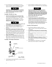
1. If Reverse Valve Bushing (18) was removed, align
notch in end of Bushing opposite the internal spline
with cast line on Housing Cover (17). The cast line is
approximately 180 from the number “5” on Oil
Chamber Plug (4) side of Housing Cover. Press the
Bushing into Cover until splined end is flush with
numbered face of Cover.
When properly installed, the notch and cast line will
be on opposite sides of the Housing Cover.
2. Make certain Reverse Valve Bushing Seals (19) are
properly located in undercuts in Reverse Valve
Bushing.
3. Dampen Reverse Valve (20) with light oil. Install
Reverse Valve Detent Spring (22) followed by Reverse
Valve Detent Ball (21) in hole in Reverse Valve. With
Impactool in an upright horizontal position and while
facing handle end of Impactool, slowly rotate Reverse
Valve and insert it from left to right in splined end of
Reverse Valve Bushing.
4. Apply a thread locking compound to Reverse Valve
Knob Screw (24). Attach Reverse Valve Knob (23) to
Reverse Valve with Reverse Valve Knob Screw, and
tighten Screw to 40 to 50 in–lb (4.5 to 5.6 Nm) torque.
Assembly of the Impact Mechanism
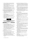
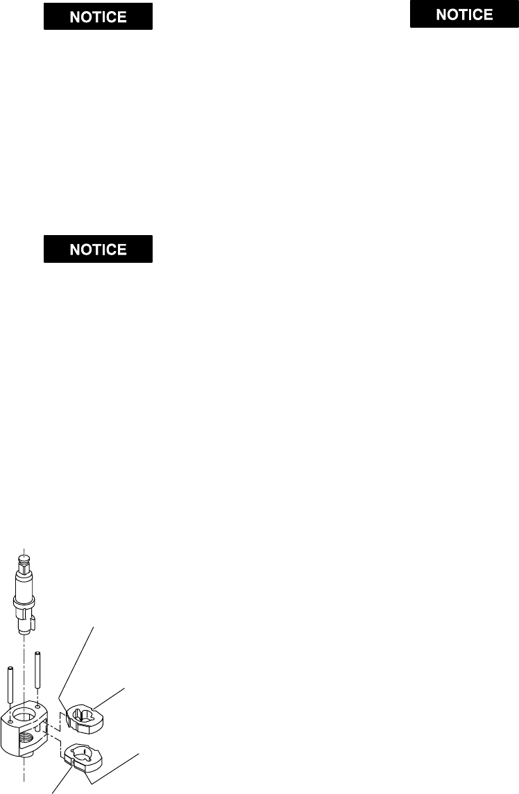
TOP HAMMER
WIDE BEVEL UP
TOP HAMMER
HALF–ROUND NOTCH ON RIGHT
BOTTOM HAMMER
WIDE BEVEL DOWN
BOTTOM HAMMER
HALF–ROUND NOTCH ON
LEFT
(Dwg. TPD652)
1. Coat Hammers (40) with a light film of Ingersoll–Rand
Impactool Grease No. 100.
2. Replace Hammers in Hammer Frame (41) exactly as
they were when you marked them prior to disassembly.
If you are installing new Hammers, or want to
change the location of the existing Hammers to
utilize both impacting surfaces, slide the Hammers
in the Hammer Frame so that the half–round notch
on one Hammer is located on one side of the Frame
and the half–round notch on the other Hammer is
located on the other side of the Frame.
3. Replace Hammer Pins (42).
4. Examine base of Anvil (48 or 100) and note its
contour. While looking down through Hammer Frame,
swing the top Hammer to its full extreme one way or
another until you can match the contour of the Anvil.
Enter the Anvil into the Hammer Frame and through
the first Hammer. Swing the bottom Hammer in
opposite direction from the top Hammer and maneuver
Anvil slightly until it drops into bottom Hammer.
Assembly of the Impactool
1. Position Motor Housing in leather–covered or
copper–covered vise jaws with splined shaft of Rotor
(32) upward.
2. Place Hammer Frame Washer (43), small hub leading,
over hub of Rotor and against the Front Rotor Bearing
(38).
3. Place assembled impact mechanism down over splined
hub of Rotor.
4. Position Hammer Case Gasket (46) against face of
Motor Housing.
5. Smear a thin film of Ingersoll–Rand No. 105 Grease on
inside surface of Hammer Case Bushing (45), and
place Hammer Case (44) down over Anvil and against
Motor Housing.
6. Install Hammer Case Cap Screws (47) and tighten
them to 60 to 70 in–lb (6.8 to 7.9 Nm) torque.
4 Form 04584272-Edition 1