


3. If Motor Clamp Washers (39) remained in Housing,
remove them. If Washers remained with motor, lift
them off Front End Plate (37).
4. Slide Front End Plate, Front Rotor Bearing (38) and
Cylinder (35) off Rotor (33) and remove Cylinder
Dowel (36) and Vanes (33).
5. Using snap ring pliers, remove Rear Rotor Bearing
Retainer (31) and slide Rear End Plate (34) and Rear
Rotor Bearing (30) off Rotor shaft.
6. If Front Rotor Bearing or Rear Rotor Bearing must be
replaced, use a drift to tap the Bearing out of End Plate.
Disassembly of the Throttle Mechanism
1. Unscrew and remove Oil Chamber Plug (4) and Oil
Chamber Plug Seal (5). Drain oil from oil reservoir.
2. Unscrew and remove Air Inlet (16).
3. Lift off Exhaust Deflector (15) and withdraw Exhaust
Silencer (l4).
4. Using snap ring pliers, remove Oiler Retaining Ring
(13) from inside handle.
5. Withdraw Oiler Body Assembly (10), Throttle Valve
Spring (9) and Throttle Valve (8) from handle.
6. Withdraw Trigger Assembly which consists of Trigger
Pin (2) and Trigger (3).
7. If Throttle Valve Seat (6) must be replaced, thread a
long 3/8” cap screw into it and pull it from handle.
Do not remove the Throttle Valve Seat unless you
have a new Seat on hand for installation. Be careful
not to lose the Throttle Valve Seat Support (7).
ASSEMBLY
General Instructions
1. Always press on the inner ring of a ball–type bearing
when installing the bearing on a shaft.
2. Always press on the outer ring of a ball–type bearing
when pressing the bearing into a bearing recess.
3. Whenever grasping a tool or part in a vise, always use
leather–covered or copper–covered vise jaws. Take
extra care with threaded parts and housings.
4. Always clean every part and wipe every part with a
thin film of oil before installation.
5. Apply a film of O–ring lubricant to all O–rings before
final assembly.
Assembly of the Throttle Mechanism
1. If Throttle Valve Seat (6) was removed, install and a
new Throttle Valve Seat by pushing Seat into place
with a 1/2” (13 mm) diameter dowel.
2. Wipe Trigger Pin (3) with some light grease, and insert
Trigger Assembly (2) into the trigger bushing.
3. Insert Throttle Valve (8), long stem end first, into
bottom of handle so that the valve stem engages hole in
Trigger Pin.
4. Install Throttle Valve Spring (9), small end first.
5. Make certain two Oiler Body Seals (12) are positioned
in annular grooves on the Oiler (10) and install Oiler,
counterbored end first, into handle. The large end of
the Throttle Valve Spring should seat in counterbore in
Oiler.
6. Install Oiler Retaining Ring (13) in groove in handle.
7. Grasp new (or solution cleaned) Exhaust Silencer (14)
by long edge. Fold it lengthwise and while squeezing
one end into a round configuration, insert it into the
handle flush with exhaust deflector recess.
8. Position Exhaust Deflector (15) on bottom of handle
and retain it with Air Inlet (16). Tighten Air Inlet to 30
to 35 ft–lb (40.5 to 47.5 Nm) torque.
Assembly of the Motor
1. Using a sleeve that will contact only the outer ring of
the bearing, press the Front Rotor Bearing (38) into
Front End Plate (37) and Rear Rotor Bearing (30) into
the Rear End Plate (34).
2. Slip Front End Plate and Bearing over splined hub of
Rotor (32).
3. Grasp splined hub of Rotor in leather–covered or
copper–covered vise jaws so that Rotor is in a vertical
position.
4. Dampen each Vane (33) with light oil and insert a Vane
into each vane slot.
5. Set Cylinder (35) over Rotor and onto Front End Plate.
6. Slide Rear End Plate and Bearing onto rotor hub and
against Cylinder.
7. Install Rear Rotor Bearing Retainer (31) in groove on
rotor hub.
8. Align dowel hole in both End Plates with one through
Cylinder, and insert a guide rod 5/32” diameter x 6”
long (3.9 mm diameter x 152 mm long). Allow rod to
protrude from Front End Plate.
9. Remove assembled motor from vise and grasp handle
of Motor Housing (1) in leather–covered or
copper–covered vise jaws so that bore of Motor
Housing is horizontal.
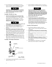
10. Place two Motor Clamp Washers (39), concave side
flat, against Front End Plate. Make certain small holes
in Washers fit onto guide rod and outer rim contacts
Front End Plate.
11. Insert protruding end of guide rod, Motor Clamp
Washers leading, into dowel hole in bore of Motor
Housing and slide motor along the rod until it is
completely seated.
12. Remove guide rod and replace it with Cylinder
Dowel (36).
13. Reposition Motor Housing in vise so that Rear End
Plate is upward.
14. Position Housing Cover Gasket (29) and Housing
Cover (17) against Motor Housing.
Form 04584272-Edition 1 3