


15
MAINTENANCE SECTION
Always wear eye protection when operating or
performing maintenance on this tool.
Always turn off the air supply and disconnect the air
supply hose before installing, removing or adjusting
any accessory on this tool, or before performing any
maintenance on this tool.
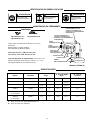
LUBRICATION
Whenever one of these Grinders is disassembled for
overhaul or replacement of parts, lubricate as follows:
1. Always wipe the Vanes (27) with a light film of oil
before inserting them into the vane slots.
2. Inject 0.5 to 1.0 cc of Ingersoll--Rand No. 10 Oil into
the Air Inlet (16) after assembly.
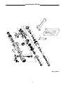
DISASSEMBLY
General Instruction:
1. Do not disassemble the tool any further than
necessary to replace or repair dama ged parts.
2. When grasping a tool or part in a vise, always use
leather--covered or copper-- covered vice jaws to
protect the surface of the part or tool and help prevent
distortion. This is particularly true of threaded
members and housings. A special rubber block is
available to hold the housing. The part number for
ordering this special block is #22040992.
3. Do not remove any part, which is a press fit in or on a
subassembly unless the removal of that part is
necessary for repairs or replacement.
4. Do not disassemble the tool unless you have a
complete set of new gaskets and O--Rings for
replacement.
5. Do not press any needle bearing from a part unless
you have a new needle bearing on hand for
installation. Needle bearings are always damaged
during the removal process.
Tool Specific Instructions:
- Steps common to all SC Models:
1. Remove the Collet Nut (36), Collet Cap (35) and
Collet (34).
2. Remove the Housing Cap (37), using Wrench
(46).
3. Remove the Motor Clamp (32).
4. Pull the Motor Assembly out of the Motor
Housing (1).
5. Disassemble the motor.
- Steps common to all XC Models:
1. Remove the Extension Housing (42).
2. Grasp the Extension Housing in a vise and
remove the Coupling Nut (39) while holding a
wrench on the flats of the Arbor (44).
3. Press the Arbor (44) out of the Extension
Housing.
4. Remove the Collet Nut (36), Collet Cap (35) and
Collet (34).
5. Remove the Bearing (41) from the rear of the
Extension Housing.
6. Press the Bearing (43) out of the front of the
Extension Housing.
7. Remove the Coupler (40) and Clamp Sleeve (38)
from the Motor Housing (1).
8. Pull the Motor Assembly out of the Motor
Housing.
9. Disassemble the motor.
Disassembly of the Motor:
1. Grasp the Cylinder (28) in a vise and use a punch to
tap the Rotor (26) out of the r ear Bearing (23).
2. Remove the Vanes (27) from the Rotor.
3. Grasp the Rotor in a vise a nd remove the Collet Body
(33) or Coupling Nut (39).
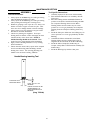
4. Remove the Front Rotor Bearing (31), if it must be
replaced, by supporting the Front End Plate (29)
between two blocks on the tabl e of an Arbor Press.
Place the blocks as close a s possible to the body of
the Rotor and press the Rotor from the Bearing and
End Plate. Remove the Front End Plate Spacer (30)
from the Rotor. Press the Bearing out of the End Plate
using a 0.433” (11mm) pin.
5. Remove the Rear Bearing (23) if it must be replaced.
Press the Bearing out of the End Plate using a 0.2375”
(6.03mm) pin.
Disassembly of the Inlet and Throttle:
1. Using a 3/4” wrench, unscrew and remove the Inlet
Bushing (16).
2. Remove the Exhaust Deflector (15), O--Ring (14) and
Silencer (13) from the Inlet.
3. Using a ¼” bushing driver, tap the Motor Housing out
of the Composite Housing (9).
4. Remove the O--Ring Gasket (8) and Muffler Element
(12).
5. Unscrew the Val ve Plug (22), and remove the Valve
Stem (18), Valve Spring (20), Valve Spring Seat (19)
and Valve O-- Ring (17).
6. The Valve Bushing (2), if it must be replaced, is only
available as pa r t of an assembly of the Motor Housing
and Bushing.
7. Press the Throttle Lever Pin (7) from the Housing and
remove the Throttle Lever Ass emb ly (3, 4, 5 and 6).
8. Any Throttle Lever parts to be replaced are only
available as part of the Throttle Lever Assembly.