


66651-B (en) Page 3 of 8
Remove the (48) screw from the (43) piston assembly.
Remove the (39) valve rod, (45) spring and (42) ball from
the (43) piston assembly.
AIR MOTOR ASSEMBLY
Place the (39) valve rod thru the (48) screw.
Clean the threads of the (39) valve rod and the (5) exten-
sion rod. Apply Loctite 271 to these threads and screw
the (5) extension rod to the (39) valve rod and tighten
by holding the (39) valve rod below the threads with an
adjustable type pliers and using a wrench on the ats of
the (5) extension rod. CAUTION: Do not mar or damage
the nish on the (5) extension rod.
Place the (42) ball and (45) spring into the (43) piston as-
sembly.
Place the (39) valve rod and (5) extension rod into the (43)
piston assembly. Apply Loctite 271 to the threads of the
(48) screw and thread the (48) screw into the (43) piston
assembly and tighten.
Assemble the (50) “O” ring to the groove in the (43) pis-
ton assembly.
Assemble the (36) “O” ring to the groove in the (46) air
motor base assembly.
Assemble the (41) “U” cup (lips up), (44) guide washer
and (40) retaining ring into the (46) base assembly.
Assemble the (43) piston assembly into the (46) base as-
sembly, being careful not to damage the (41) “U” cup.
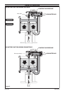
Lubricate the inside diameter of the (37) air cylinder and
slide it down over the (43) piston assembly and onto the
(46) air motor base assembly (see gure 4).
Assemble the (36) “O” ring to the groove in the (22) head
plate.
Align the notch in the (22) head plate with the port in
the (46) air motor base assembly and press the (22) head
plate down until it is seated against the (37) air cylinder.
Assemble eight (49) cap screws thru the (22) head plate
and (46) air motor base assembly.
Assemble eight (47) nuts on the (49) cap screws and
tighten alternately and evenly.
Assemble two (7) “O” rings to the grooves in the (6) cylin-
der.
Assemble the (24) “U” cup into the (6) cylinder, with the
lips facing out.
Assemble the (6) cylinder over the (5) extension rod and
into the (22) head plate. NOTE: Assemble the (6) cylinder
with the “U” cup end onto the (5) extension rod rst.
Assemble the (4) washer over the (5) extension rod and
into the (6) cylinder.
Clean the threads on the (2) piston assembly. Apply
Loctite 271 to the threads and assemble to the (5) exten-
sion rod and tighten, using the wrench ats. CAUTION:
Do not mar or damage the surface of either of these
parts.
Assemble the (1 and 3) “O” rings to the grooves in the (2)
piston assembly.
Assemble the (14) “U” cup into the (13) gland, with the
lips pointed into the gland. Lubricate the bore of the (30)
block manifold and assemble the (13) gland into the (30)
block manifold, with the lips of the (14) “U” cup pointed
into the block manifold. NOTE: Be sure the (13) gland is
seated squarely against the shoulder in the (30) block
manifold.
28.
29.
1.
2.
3.
4.
5.
6.
7.
8.
9.
10.
11.
12.
13.
14.
15.
16.
17.
18.
19.
20
.
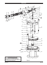
AIR MOTOR DISASSEMBLY
NOTE: All threads are right hand.
Place the air motor in an up-stroke position by pushing
(43) piston assembly toward the top of the motor.
Remove six (26) cap screws from the top of (27 and 30)
blocks.
Remove (27 and 30) blocks from (22) head plate.
Remove (34) tube from (46) base assembly. Remove two
(33) “O” rings from (34) tube and one (33) “O” ring from
the bottom of (30) block manifold.
Remove four (26) cap screws from the end of (27) block.
Separate (27) block from (30) block manifold and remove
(28 and 29) “O” rings.
Remove 3/4 - 14 N.P.T. pipe plugs from the two exhaust
ports, if applicable.
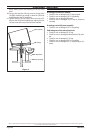
Using a 1/2” socket on (8) cap screw, turn (20) spool
clockwise to align opening or slot in (20) spool with the
3/4 - 14 N.P.T. exhaust port nearest the (8) cap screw.
Insert a 1/4” rod or similar device thru the exhaust port of
(30) block manifold and into the opening or slot of (20)
spool. This rod will prevent rotation of (20) spool when
removing (8) cap screw and (9) washer. CAUTION: Do
not permit this rod to rest against (17) spacer legs,
which could cause breakage of (17) spacer.
Remove (8) cap screw and (9) washer.
Unscrew four (32) cap screws and remove (31) cap as-
sembly.
Remove (20) spool out the “exhaust end” of (30) block
manifold and remove (11) piston out the other end.
From the “exhaust end” of (30) block manifold, remove
four (19) washers, four (17) spacers, four (18) “O” rings,
ve (15) “O” rings, (16) washer, (14) “U” cup, (13) gland and
(10) “O” ring.
Remove (12) “U” cup from (11) piston.
Using the wrench flats provided, remove the (2) piston
assembly from the (5) extension rod.
Remove (1 and 3) “O” rings from (2) piston assembly.
Remove (4) washer, (6) cylinder, two (7) “O” rings and (24)
“U” cup from (22) head plate.
Remove two (7) “O” rings and (24) “U” cup from (6) cylin-
der.
Remove eight (47) nuts from (49) cap screws.
Remove eight (49) cap screws from (22) head plate and
(46) air motor base assembly.
Remove (22) head plate from (37) air cylinder, then re-
move (36) “O” ring from (22) head plate.
Pull upward on (37) air cylinder until (43) piston assem-
bly separates from the (46) base assembly. If, in this step,
the (43) piston assembly is not pulled from the (46) base
assembly, then remove it after removing the (37) air cyl-
inder.
If the (37) air cylinder and (43) piston assembly are re-
moved as one unit, then remove the (43) piston assembly
from the (37) air cylinder.
Remove the (36) “O” ring from the (46) base assembly.
Remove (40) retaining ring, (44) guide washer and (41) “U”
cup from (46) base assembly.
Remove the (50) “O” ring from the (43) piston assembly.
Unscrew (5) extension rod from (39) valve rod by holding
the (39) valve rod with an adjustable type pliers and us-
ing a wrench on the wrench ats provided at the top of
the (5) extension rod.
1.
2.
3.
4.
5.
6.
7.
8.
9.
10.
11.
12.
13.
14.
15.
16.
17.
18.
19.
20.
21.
22.
23.
24.
25.
26.
27
.
DISASSEMBLY / ASSEMBLY