


Page 8 of 8 66651-B (en)
PN 97999-869
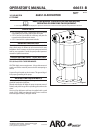
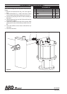
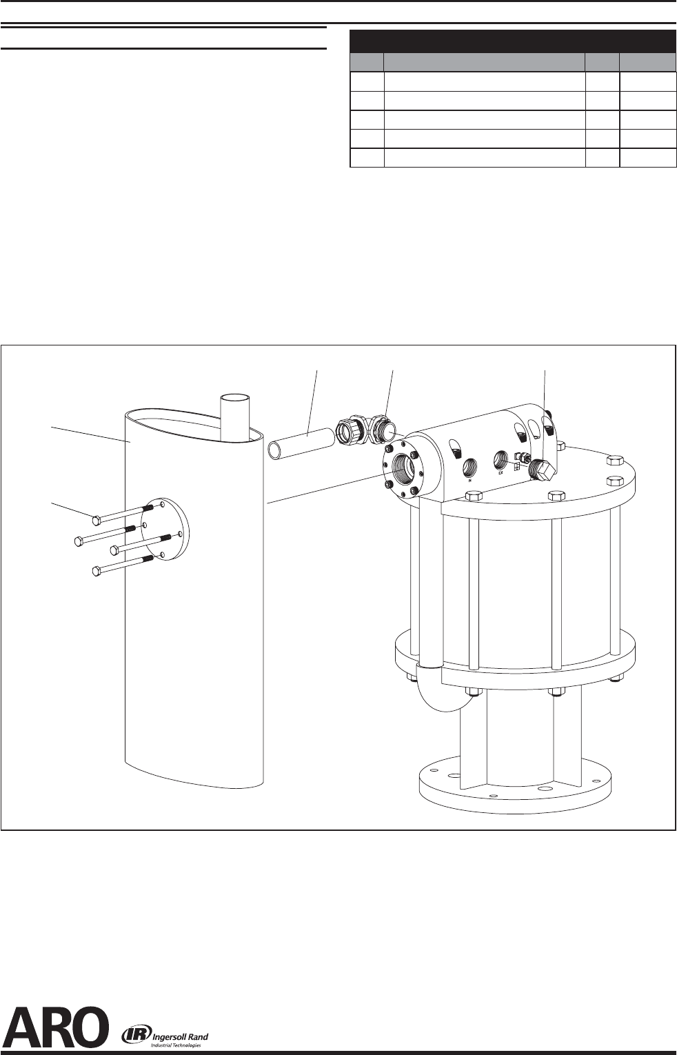
OPTIONAL 66718 MUFFLER ASSEMBLY
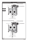
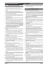
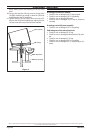
MUFFLER INSTALLATION
NOTE: Secure ttings after all components have been posi-
tioned.
Remove nut and sleeve from the (1) 90° short angle el-
bow.
Insert and install the 3/4 - 14 N.P.T. end of the (1) elbow
to the air motor (back o the retaining nut a few turns).
Insert the (5) pipe plug into the air motor secondary ex-
haust port.
Slide the sleeve and nut onto the (2) tube and insert the
tube into the (1) elbow.
Locate the (3) mu er on the collar of the air motor while
aligning the (2) tube with the hole provided in the muf-
er.
Secure the muffler to the air motor collar with four (4)
cap screws.
Secure all connections.
1.
2.
3.
4.
5.
6.
7
.
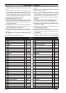
66718 PARTS LIST
Item Description
(size)
Qty Part No.
1 90° EMT Short Angle Elbow (1) 79294
2 Tube (1) 79293
3 Mu er (1) 79295
4 Cap Screw
(
1/4” - 20 x 4”
)
(4) Y6-417
5 Pipe Plug
(3/4 - 14 N.P.T.)
(1) Y17-14-C
125
4
3
Figure 6