


Page 4 of 8 66651-B (en)
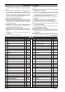
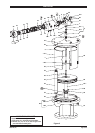
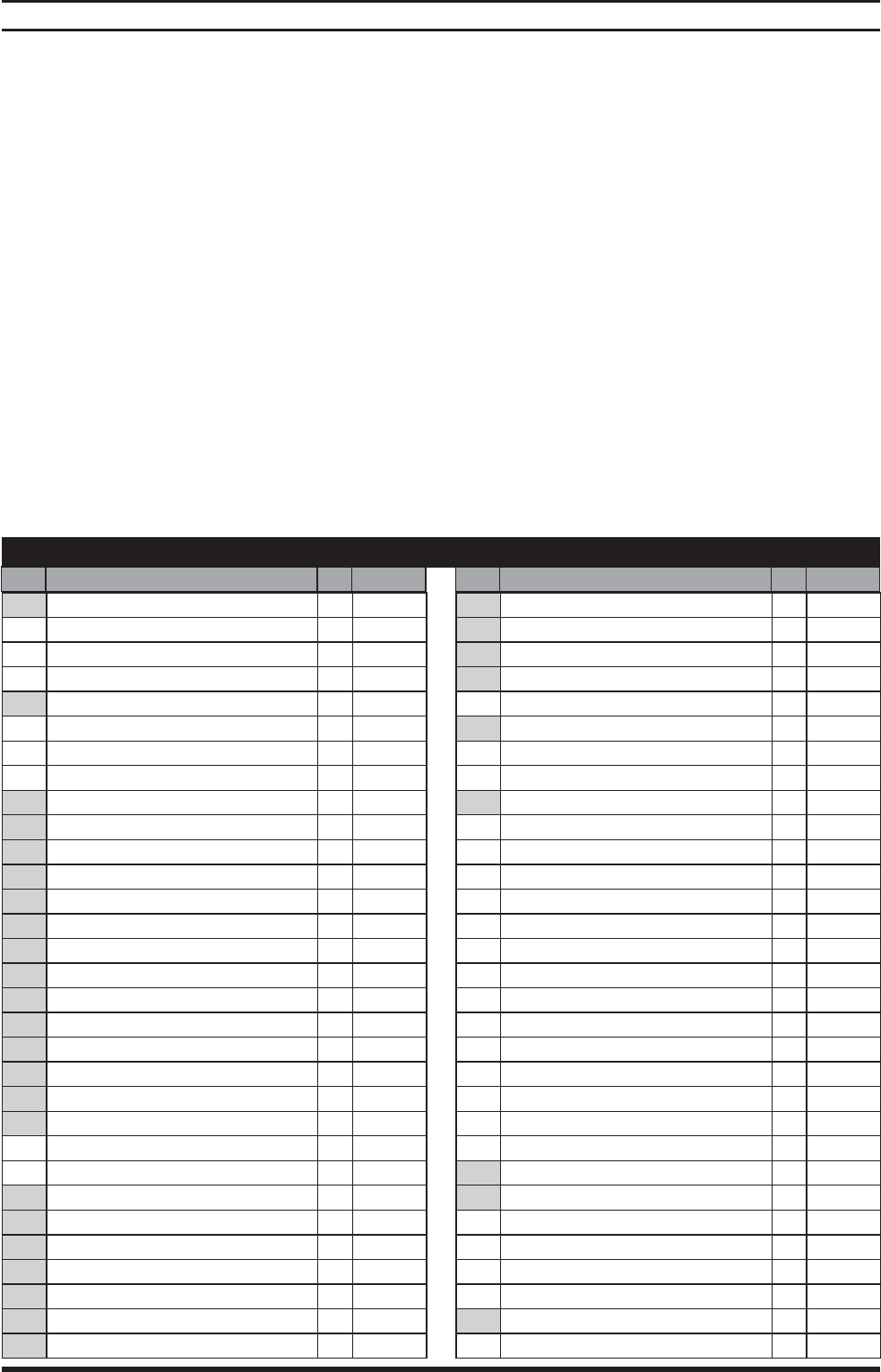
PARTS LIST
Item Description
(size)
Qty Part No. Item Description
(size)
Qty Part No.
9
1 "O" Ring
(1/16" x 5/16" o.d.)
(1) Y325-8
2 Piston Assembly
(includes items 2a and 2b)
(1) 66654
2a Washer (1) 92524
2b Piston (1) 92520
9
3 “O” Ring
(3/32” x 5/8” o.d.)
(1) Y325-111
9
4 Washer (1) 92517
5 Extension Rod (1) 92519
6 Cylinder (1) 92513
9
7 “O” Ring
(1/16” x 7/8” o.d.)
(2) Y325-18
8 Cap Screw, Hex Head
(5/16” - 18 x 7/8”)
(1) Y6-54-C
9 Washer (1) F15-44-C
9
10 “O” Ring
(1/16” x 1/2” o.d.)
(1) Y325-12
11 Piston (1) 92521
9
12 “U” Cup Packing
(3/16” x 1-5/8” o.d.)
(1) Y186-53
13 Gland (1) 94789
9
14 “U” Cup Packing
(3/16” x 1-1/2” o.d.)
(1) Y186-52
9
15 “O” Ring
(3/32” x 2-1/16” o.d.)
(5) Y325-134
16 Washer (1) 94790
17 Spacer (4) 93250
9
18 “O” Ring
(1/8” x 1-3/4” o.d.)
(4) Y325-222
19 Washer (4) 93251
20 Spool (1) 92522
22 Head Plate (1) 92529
9
24 “U” Cup Packing
(1/8” x 11/16” o.d.)
(1) Y186-46
25 Pipe Plug
(1/8 - 27 N.P.T.)
(2) Y227-2-L
26 Cap Screw, Socket Head
(3/8” - 16 x 2-1/2”)
(10) Y99-68
27 Block (1) 92514
9
28 “O” Ring
(1/16” x 5/8” o.d.)
(1) Y325-14
9
29 “O” Ring
(3/32” x 1-7/8” o.d.)
(1) Y325-131
30 Block Manifold (1) 92515
31 Cap Assembly
(includes items 31a and 31b)
(1) 66655
31a Cap (1) 92531
31b Washer (1) 92516
32 Cap Screw, Socket Head
(1/4” - 20 x 1-3/4”)
(4) Y99-45
9
33 “O” Ring
(1/16” x 1-1/4” o.d.)
(3) Y325-24
34 Tube (1) 92518
35 Pipe Plug
(1/8 - 27 N.P.T.)
(1) Y227-2-L
9
36 “O” Ring
(1/8” x 9-3/4” o.d.)
(2) Y325-272
37 Air Cylinder (1) 92217
38 Pipe Plug
(1/16 - 27 N.P.T.)
(1) Y227-1-L
39 Valve Rod (1) 92527
40 Retaining Ring
(2.630” o.d.)
(1) Y147-237
9
41 “U” Cup Packing
(1/4” x 1-3/4” o.d.)
(1) Y186-24
42 Ball
(0.4375” dia.)
(1) Y16-14
43 Piston Assembly (1) 62110-B
44 Guide Washer (1) 92216
45 Spring (1) 24143-B
46 Air Motor Base Ass’y
(includes items 46a and 46b)
(1) 66652
46a Air Motor Base (1) 92530
46b Bushing (1) 92511
47 Nut
(1/2” - 20)
(8) Y11-8-C
48 Screw (1) 92525
49 Cap Screw, Hex Head
(1/2” - 20 x 10-1/4”)
(8) 94046-1
9
50 “O” Ring
(1/4” x 10” o.d.)
(1) Y325-448
51 Spacer (1) 92860
52 Connector (1) 93006
9
Cotter Pin
(1/8” x 2”)
(1) Y15-47-C
9
Gadus S2 U1000 Grease Packet (1/4 oz.) (2) 94833
9
Items included in service kit 637110
Service Kit
(entire valve section)
637111
Items not included with 66651-B air motor
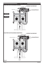
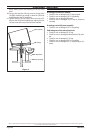
Assemble one (15) “O” ring and the (16) washer into the
(30) block manifold and against the (13) gland (see gure
5).
Assemble four (15) “O” rings, four (18) “O” rings, four (17)
spacers and four (19) washers into the (30) block mani-
fold (see gure 5). NOTE: Assemble the (19) washers with
the i.d. lips toward the (18) “O” ring. Position the (17)
spacers so the legs are not aligned with the 3/4 - 14 N.P.T.
exhaust ports in the (30) block manifold.
Clean the threads in the (20) spool.
Apply grease to the exterior of the (20) spool and assem-
ble it into the (30) block manifold. Align the slot in the (20)
spool with the 3/4 - 14 N.P.T. exhaust port in the side of
the (30) block manifold.
Assemble the (51) spacer into the (31) cap assembly and
assemble the (31) cap assembly to the (30) block mani-
fold, securing with four (32) cap screws.
Assemble the (12) “U” cup into the groove in the (11)
piston, with the lips pointed toward the “boss” side of the
piston.
Assemble the (10) “O” ring onto the boss portion of the
(11) piston.
Clean the threads on the (8) cap screw.
21.
22.
23.
24.
25.
26.
27.
28.
Assemble the (8) cap screw and (9) washer thru the (11)
piston.
Apply Loctite 271 to the threads of the (8) cap screw then
thread it into the (20) spool.
Insert a 1/4” rod or similar device thru the 3/4 - 14 N.P.T.
exhaust port in the side of the (30) block manifold and
thru the slot of the (20) spool to prevent it from rotating,
then tighten the (8) cap screw. Remove the 1/4” rod.
Assemble the (28 and 29) “O” rings into the (30) block
manifold.
Assemble the (27) block to the (30) block manifold, se-
curing with four (26) cap screws (hand tight only).
Assemble two (33) “O” rings to grooves in the (34) tube.
Assemble the (34) tube into the port provided in the (46)
air motor base assembly.
Assemble one (33) “O” ring to the counterbore in the bot-
tom of the (30) block manifold.
Lubricate the bore in the (27) block.
Carefully slide the (27 and 30) block assemblies down
over the (2) piston assembly and (34) tube and onto the
(22) head plate.
Assemble six (26) cap screws in the (27 and 30) block
assemblies. Tighten the two (26) cap screws in the (27)
29.
30.
31.
32.
33.
34.
35.
36.
37.
38.
39
.
DISASSEMBLY / ASSEMBLY
(continued on page 6)