


FEED RATE CONTROL VALVES
l
Turn valve (24) marked “R” on top of housing, approximately
1-1/2 turns counterclockwise (open).
l
Turn the other valve (24) marked “F" on top of housing, clock-
wise until closed (do not tighten too snugly).
l
Start the unit and slowly turn valve (24) marked “F", counter-
clockwise (open) until the desired forward rate of feed is
reached.
l
A final adjustment of the rate of return (retract) can be made
with the valve (24) marked “R” on housing.
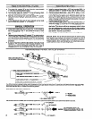
MANUAL OPERATION
l
Install button bleed valve (27) in either the “F" port located at
top of valve housing or the “F" port located at the rear of valve
housing. NOTE: Unused port must be plugged with pipe plug
(22).
l
Depress button bleed valve (27) marked “F" on valve housing.
The unit will start in the forward (advancing) mode and contin-
ue to feed forward until the adjusting screw “B” has depressed
bleed valve (27) marked “R” to retract the unit. See set-up
procedure.
l
A manual emergency retract button bleed valve (27) can be
installed in “R” port at top of valve housing if desired. This
valve can be used to immediately retract the unit in case of
misaligned part or other emergency. Valve not furnished.
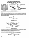
REMOTE OPERATION
Install a pressure bleed valve - ARO part number 9600 - in
valve port marked “F" at either the top or rear of valve housing
Connect pressure bleed valve - using 1/8” i.d. tubing - to a re-
mote operated valve which, when actuated, feeds air pres-
sure to the pressure bleed valve. Pressure bleed valve will
bleed the air from "F" port of valve housing causing spool
valve in housing to shift to the forward feed position, thus start-
ing the forward stroke of the unit.
Install a pressure bleed valve - ARO part number 9600 - in
valve port marked “R” at the top of the valve housing and con-
nect - using 1/8” i.d. tubing -to a remote MANUALLY oper-
ated valve. This valve is used as an emergency retract in case
of a part misalignment or such only as the unit, when properly
set-up and applied, will automatically retract and return to the
start position. See set-up procedure.
Refer to page 10 for plumbing and schematic diagrams.
SPECIAL NOTE: The air inlet and remote ports of valve housing
have tapered pipe threads and should not require the use of
thread sealants, such as sealant tape or pipe joint compounds.
Thread sealants, when used improperly, can contaminate air pas-
sages and cause valve or unit to malfunction.
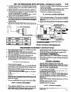
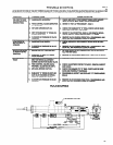
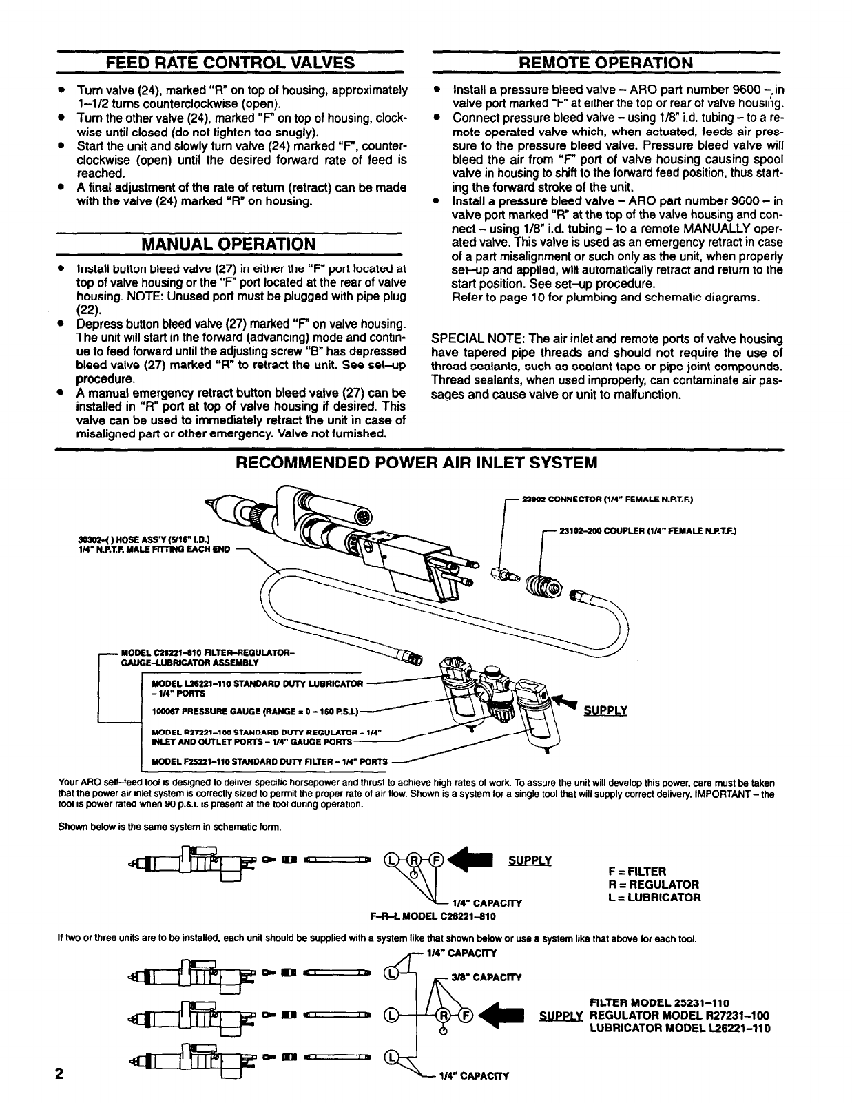
RECOMMENDED POWER AIR INLET SYSTEM
Your ARO self-feed tool is designed to deliver specific horsepower and thrust to achieve high rates of work. To assure the unit will develop this power, care must be
that the power air inlet system is correctly sized to permit the proper rate of air flow. Shown is
a
system for a single tool that will supply correct delivery. IMPORTANT
tool is power rated when 90 p.s.i. is present at the tool during operation.
taken
‘-the
Shown below is the same system in schematic form.
SUPPLY
F = FILTER
R = REGULATOR
L = LUBRICATOR
If two or three units are to be installed, each unit should be supplied with a system like that shown below or use a system like that above for each tool.
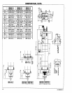
1/4” CAPACITY
3/8” CAPACITY
1/4” CAPACITY
FILTER MODEL 25231-110
REGULATOR MODEL R27231-100
LUBRICATOR MODEL L26221-110