


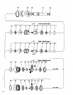
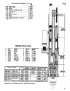

DISASSEMBLY/ASSEMBLY INSTRUCTIONS
Lubricate needle bearing (103) with ARO 33153 grease and as-
semble to spindle (104) and assemble spindle to ring gear (102).
Assemble seal (91) to lock nut (90) and assemble lock nut to
ring gear, securing bearings and spindle.
Assemble spindle nut (92) to spindle.
Assemble gears (82) to spindle, securing with shafts (81).
Assemble spacer (99) and bearing (70) to spindle, securing
shafts.
Assemble gears (73 and 75) to spindle, securing with shafts
(72) and retaining ring (101). NOTE: Be sure each shaft con-
tains 15 needle bearings.
Lubricate gears liberally with ARO 33153 grease and as-
semble spindle to ring gear.
Assemble gearing to tool.
Assemble chuck (117) to spindle.
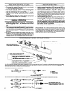
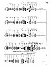
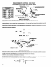
MOTOR DISASSEMBLY
Remove gearing from tool as previously outlined.
Remove spacer (88) and motor assembly from housing.
Remove cap (54) and shield (55).
Grasp cylinder in one hand and tap splined end of rotor with a
soft face hammer; motor will come apart.
MOTOR ASSEMBLY
Assemble bearing (56) to end plate (57), pressing on outer
race of bearing.
Assemble end plate (57) to rotor, pressing on inner race of
bearing.
Coat i.d. of cylinder (61) with ARO 29665 spindle oil and as-
semble cylinder to end plate (57), aligning roll pin in cylinder
with hole in end plate.
Coat blades (59 or 66) with ARO 29665 spindle oil and insert
into rotor slots - straight side out.
Assemble bearing (63) to end plate (62), pressing on outer
race of bearing.
Assemble end plate (62) to cylinder, pressing on inner race of
bearing.
Be sure rotor does not bind (if rotor binds, tap splined end of
rotor lightly to loosen).
Assemble shield (55) and cap (54) to end plate (57).
Assemble motor and spacer (68) to motor housing.
Assemble gearing to tool.
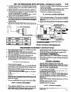
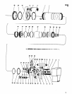
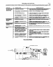
AIR PISTON DISASSEMBLY
Remove gearing and motor assembly as outlined.
Remove cover (1) adapter (3) washer (4) and trip bracket (5).
Place valve housing in a suitable holding device with the outer
sleeve in an upright position.
Using a strap wrench on outer sleeve (43), unthread (L.H.
threads) and CAUTIOUSLY remove outer sleeve straight up
and off from valve housing to prevent bending of air cylinder
(37) and damaging the inside diameter.
Handle the air cylinder (37) with care so its fine cylindrical
shape is not distorted in any manner.
If the air cylinder remains inside the outer sleeve when the
sleeve is removed, push the piston rod (51) forward then pull it
backward. The cylinder will then extend from the sleeve and
can now be removed.
Remove “0” ring (33) and retaining ring (34).
Push piston rod and motor housing out thru gear end of outer
sleeve. Piston (36) will drop out when motor housing and pis-
ton rod are removed from outer sleeve.
Insert a suitable rod thru gear end of outer sleeve and push
muffler cap (41) out thru valve end of outer sleeve.
Piston rod (51) and motor housing (52) are secured with a hard
drying thread adhesive. If it should become necessary to sepa-
rate these two parts, heat the threaded area lightly to soften the
adhesive and unthread the rod from the housing (R.H. threads).
AIR PISTON ASSEMBLY
NOTICE: When a part containing “0” rings has been removed
from the tool, it is recommended that the “0” rings be replaced
with new ones when reassembling the part to the tool. Lubricate
all “0” rings with ARO 36460 “0” ring lubricant.
Assemble retaining ring (38) “0” ring (39), “0” ring (40) and
screen (42) to muffler cap (41).
Assemble muffler cap (41), screened end first, to outer sleeve
(43) from end of sleeve with internal threads. Push muffler cap
into sleeve until it bottoms against step in sleeve.
Coat torque pin (44) with grease to retain pin in place and as-
semble inside outer sleeve in hole provided.
Assemble “0” ring (50) to piston rod.
Assemble motor housing and piston rod to outer sleeve thru
end of sleeve with external threads and push piston rod thru
muffler cap, using care not to damage “0” ring (39) contained
in muffler cap. Align slot in motor housing with torque pin (44).
Assemble seals (35) to piston (36), with lips of seals facing
away from each other.
Assemble piston (36) to piston rod (51) and push piston on rod
until it seats against “0” ring (50) and step on rod.
Assemble retaining ring (34) to groove in piston rod, securing
piston on rod.
Assemble “0” ring (33) to piston rod and slide on rod until it
seats against retaining ring (34).
Clamp valve housing (10) in a suitable holding device, with the
threaded end of housing upright.
Coat i.d. of air cylinder (37) with “0” ring lubricant 36460 and
place air cylinder on valve housing (10) over "0" ring (30).
Using care not to damage “0” rings (11) contained in housing,
insert piston rod (51) thru housing and carefully locate outer
sleeve over air cylinder and thread sleeve to housing. Tighten
securely using a strap wrench.
Assemble motor, gearing, trip bracket and components and
assemble cover (1) to housing.
VALVE HOUSING DISASSEMBLY
The valve body (14), feed control valves (24) and button bleed
valves (27) can be serviced without removing outer sleeve from
valve housing. To gain access to check valves (17) and compo-
nents or “0” rings (11), follow disassembly procedure for remov-
ing the air piston.
Remove both caps (12) and “0” rings (13) - models 8255-A-( )
only.
Push valve body (14) out thru housing. Handle valve body
with reasonable care so the o.d. of valve is not damaged.
Button bleed valves (27) need not be removed except for re-
placement.
VALVE HOUSING ASSEMBLY
Replace all “0” rings with new ones.
Lubricate “0” rings (15) with 36460 lubricant and assemble to
valve body - models 8255-A-( ) only.
Assemble valve body to housing and assemble caps (12)
with “0” rings (13), to housing.
If check valve(s) (17) have been removed, assemble “0"
ring(s) (16) to valve(s) and assemble valve(s) to housing.
Assemble spring(s) (18) to housing.
Assemble “0” ring (20) to screw plug (21) and assemble to
housing.
Assemble screw plug (19) to housing - models 8255A-( ) only
Assemble outer sleeve and components to housing as de-
scribed in air piston assembly section.
Assemble “0” rings (23) to needle valves (24) and assemble
needle valves to housing.
Assemble plate (25) to housing, securing with screws (26).
4