


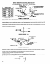
SET-UP PROCEDURE WITH OPTIONAL HYDRAULIC CHECK
M103
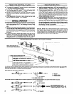
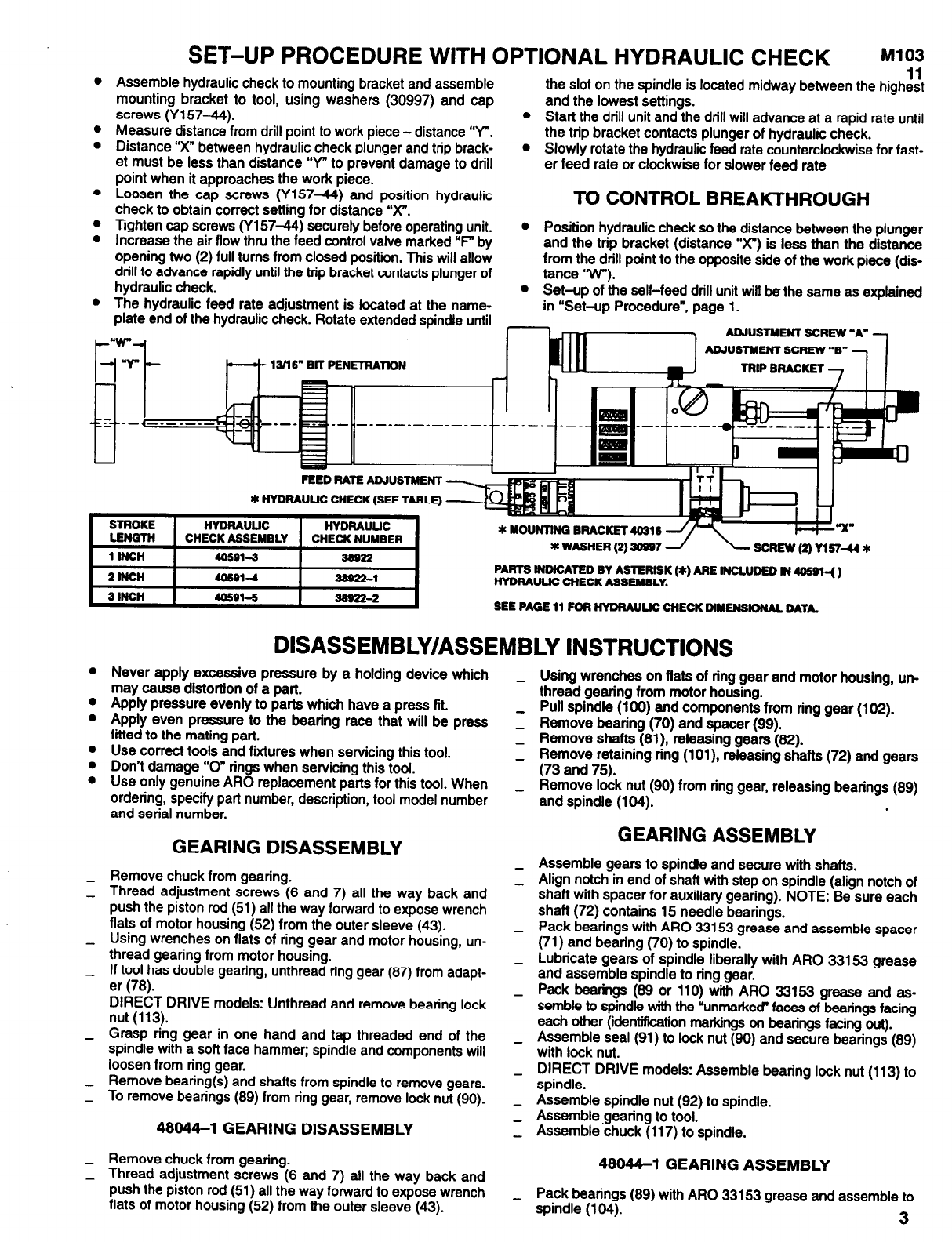
Assemble hydraulic check to mounting bracket and assemble
mounting bracket to tool, using washers (30997) and cap
screws (Y157-44).
Measure distance from drill point to work piece - distance “Y".
Distance “X” between hydraulic check plunger and trip brack-
et must be less than distance “Y" to prevent damage to drill
11
the slot on the spindle is located midway between the highest
and the lowest settings.
l
Start the drill unit and the drill will advance at a rapid rate until
the trip bracket contacts plunger of hydraulic check.
l
point when it approaches the work piece.
Slowly rotate the hydraulic feed rate counterclockwise for fast-
er feed rate or clockwise for slower feed rate
Loosen the cap screws (Y15744) and position hydraulic
check to obtain correct setting for distance “X”.
Tighten cap screws (Y157-44) securely before operating unit.
Increase the air flow thru the feed control valve marked “F" by
opening two (2) full turns from closed position. This will allow
drill to advance rapidly until the trip bracket contacts plunger of
hydraulic check.
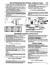
TO CONTROL BREAKTHROUGH
The hydraulic feed rate adjustment is located at the name-
plate end of the hydraulic check. Rotate extended spindle until
l
Position hydraulic check so the distance between the plunger
and the trip bracket (distance "X”) is less than the distance
from the drill point to the opposite side of the work piece (dis-
tance "W").
l
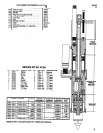
FEED BATE ADJUSTMENT
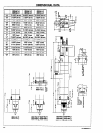
SEE PAGE 11 FOB HYDRAULIC CHECK DIMENSIONAL DATA.
l
l
l
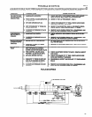
DISASSEMBLY/ASSEMBLY INSTRUCTIONS
Never apply excessive pressure by a holding device which
may cause distortion of a part.
Apply pressure evenly to parts which have a press fit.
Apply even pressure to the bearing race that will be press
fitted to the mating part.
Use correct tools and fixtures when servicing this tool.
Don’t damage “0” rings when servicing this tool.
Use only genuine ARO replacement parts for this tool. When
ordering, specify part number, description, tool model number
and serial number.
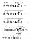
GEARING DISASSEMBLY
Remove chuck from gearing.
Thread adjustment screws (6 and 7) all the way back and
push the piston rod (51) all the way forward to expose wrench
flats of motor housing (52) from the outer sleeve (43).
Using wrenches on flats of ring gear and motor housing, un-
thread gearing from motor housing.
If tool has double gearing, unthread ring gear (87) from adapt-
er (78).
DIRECT DRIVE models: Unthread and remove bearing lock
nut (113).
Grasp ring gear in one hand and tap threaded end of the
spindle with a soft face hammer; spindle and components will
loosen from ring gear.
Remove bearing(s) and shafts from spindle to remove gears.
To remove bearings (89) from ring gear, remove lock nut (90).
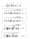
48044-1 GEARING DISASSEMBLY
Remove chuck from gearing.
Thread adjustment screws (6 and 7) all the way back and
push the piston rod (51) all the way forward to expose wrench
flats of motor housing (52) from the outer sleeve (43).
-
Using wrenches on flats of ring gear and motor housing, un-
thread gearing from motor housing.
Pull spindle (100) and components from ring gear (102).
Remove bearing (70) and spacer (99).
Remove shafts (81). releasing gears (82).
Remove retaining ring (101), releasing shafts (72) and gears
(73 and 75).
Remove lock nut (90) from ring gear, releasing bearings (89)
and spindle (104).
GEARING ASSEMBLY
Assemble gears to spindle and secure with shafts.
Align notch in end of shaft with step on spindle (align notch of
shaft with spacer for auxiliary gearing). NOTE: Be sure each
shaft (72) contains 15 needle bearings.
Pack bearings with ARO 33153 grease and assemble spacer
(71) and bearing (70) to spindle.
Lubricate gears of spindle liberally with ARO 33153 grease
and assemble spindle to ring gear.
Pack bearings (89 or 110) with ARO 33153 grease and as-
semble to spindle with the ‘unmarked” faces of bearings facing
each other (identification markings on beatings facing out).
Assemble seal (91) to lock nut (90) and secure bearings (89)
with lock nut.
DIRECT DRIVE models: Assemble bearing lock nut (113) to
spindle.
Assemble spindle nut (92) to spindle.
Assemble gearing to tool.
Assemble chuck (117) to spindle.
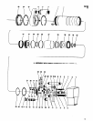
48044-1 GEARING ASSEMBLY
Pack bearings (89) with ARO 33153 grease and assemble to
spindle (104).
3