


2 45527801_ed1
WARNING
Always wear eye protection when operating or performing maintenance on this tool.
Always turn o the air supply and disconnect the air supply hose before installing, removing or adjusting any accessory on this tool or
before performing any maintenance on this tool.
Note: (When reading the instructions, refer to exploded diagrams in parts Information Manuals when applicable (see under Related Documentation
for form numbers).
Clutch Spring Selection Chart
Model ES45
Part Number Torque Range
ES50T-43 1 0.3 to 2.6 in-lb (0.04 to 0.30 N m)
ES50T-462 1.2 to 6.5 in-lb (.I4 to .74 N m)
Model ES50T and ES50TC
Part Number Torque Range
ES50T-431 0.5 to 3.0 in-lb (0.06 to 0.34 N m)
ES50T-462 2.0 to 9.0 in-lb (0.23 to 1.02 N m)
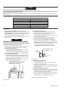
Disassembly
For Models ES45T and ES5OT, unscrew and remove the
Coupling (55). This is a left-hand thread; turn clockwise to remove.
For Model ES5OTC, unscrew and remove the Nose Collar (61).
Using a Phillips Screwdriver, remove the three Housing Screws (2).
This is a left-hand thread; turn clockwise to remove.
Carefully separate the right side of the Housing from the left side
of the Housing.
NOTICE
The Model ES5OTC Screwdriver housing is assembled using a
liquid gasket as a sealing material. Carefully pry the housing
sections apart using a thin, at piece of metal. Do not use heat or
chemical solutions to seperate the two halves.
4. Lifting the spindle end of the assembly slightly, carefully pull the
Gear Case (37) and assembled clutch away from the Motor.
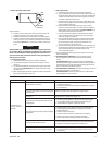
5. Trigger Switch (8) replacement
Lift the Trigger Switch out of its recess in the left side of the
Housing (1) and unsolder the connections.
Solder the leads to a new Trigger Switch and reposition the
Switch in the Housing. (Refer to the wiring diagram below).
6. Reverse Switch (9) replacement
The Reverse Switch is tted into the left side of the Housing.
Remove the Switch by depressing the locking tab of the
switch mount from the rear with a at blade Screwdriver and
pushing the Switch out of the Housing.
Unsolder the wiring to the Switch and install a new Switch.
(Refer to the wiring diagram below).
GREEN
BLUE
BLUE
BL
UE
RED
RED
MOTOR
FORWARD/REVERSE SWITCH
(VIEWED FROM REAR)
M
RED
RED
RED
BLACK
4
3
3
2
2
1
1
5
2
1
POWER CORD
BRAKE SWITCH
TRIGGER SWITCH
WHITE
YELLOW
Wiring diagrams for ES45T, ES50T and
ES50TC Electric Screwdrivers
(Dwg. TPD1114)
1.
2.
3.
a.
b.
a.
b.
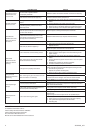
7. Brake Switch (15) replacement
Remove the two Screws (16) holding the Brake Switch.
Unsolder the wiring to the Brake Switch and install a new
Switch. (Refer to the wiring diagram above).
Position the Brake Switch and install the two Screws to secure
it to the Shuto Switch Plate (10).
After installing the Brake Switch, loosen the Switch Plate
Screw (11) that holds the Switch Plate in the Housing.
Move the Switch Plate toward the Motor and tighten the
Screw when the Switch is pushed .014 + or -.002 beyond the
“ON” point (point that the Switch clicks). Placing a .014” shim
on the arm of the Switch and moving the Switch until it clicks
is a simple method of setting the Brake Switch gap.
BRAKE
SWITCH
SWITCH PLATE
SCREW
Models ES45T, ES50T and ES50TC Electric Screwdrivers
.014 ± .002
“ON” POINT (SWITCH “CLICKS”)
(Dwg. TPD1113)
8. Brush Assembly (24) replacement
Unsolder the brush lead.
Lift the brush spring end upward and over the corner of the
phenolic tab. Remove the brush.
Solder the brush lead onto a new brush, install the brush and
reposition the brush spring. (d) Repeat steps (a), (b) and (c) for
the remaining brush.
9. Power Cord Assembly (6) replacement
Unsolder the wires to the Trigger Switch (S), Brake Switch (15)
and the green and yellow wires of the Power Cord where the
leads from the Reverse Switch (9) are spliced.
Install a new Power Cord Assembly and solder the wires to the
Trigger Switch, Brake Switch and two leads from the Reverse
Switch as shown in the wiring diagram on page 12.
* Trademark of Permabond International.
a.
b.
c.
d.
e.
a.
b.
c.
a.
b.