


45527801_ed1 3
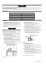
10. Motor Assembly replacement
NOTE HOLE
LOCATION
BLUE
RED
(Dwg. TPD1052)
Unsolder the two motor leads. Note the location of the red
and blue leads to the hole in the side of the motor.
Solder the motor leads to a new motor as illustrated above.
Carefully check the Reverse Switch (9) to make sure that the
motor runs in the correct rotation as indicated on the Switch.
If the motor does not run in the correct rotation, reverse the
leads.
NOTICE
Model ES5OTC has a Shield Plate (20) separating the motor from
the switches. When installing the assembled motor, make certain
Perma-Lok GasketMaker* HH190 liquid gasket material forms a
seal around the edge of the Plate and also at the opening in the
Plate for the motor leads.
11. Pushrod replacement
Remove the Gear Case (37) from the Motor Assembly.
Pull the Pushrod (35) out of the motor and replace it with a
new one.
Pull the Pushrod (46) out of the Gear Case. Lightly coat a new
Pushrod with Ingersoll Rand No. 67 Grease and insert it into
the Gear Case.
After replacing both Pushrods, adjust the timing of the Switch
Plate (10) as described in Step 7(e).
a.
b.
c.
a.
b.
c.
d.
12. Gear replacement
Pull the Gear Case (37) away from the Motor Assembly.
The joint between the Gear Case and Clutch Housing (53) is a
left-hand thread. Using one wrench on the gear case ats and
another on the ats of the Clutch Housing, turn the Housing
clockwise to separate the two parts.
Remove the Cam (43), two Cam Pins (44), Thrust Washer (42),
Spindle Assembly (40) and Gear Head Assembly (38) from the
clutch end of the Gear Case.
Inspect the Gear Head Planet Gears (39), Spindle Planet
Gears (41) and the gear teeth in the Gear Case for chipped or
broken teeth. Apply a small amount of Ingersoll Rand No. 67
Grease to the Gears, Gear Case and Cam.
Insert the Gear Head Assembly, Planet Gears rst, into the
clutch end of the Gear Case. Make certain the Planet Gears
mesh with the gear case spline.
Insert the Spindle Assembly, gear end leading, into the Gear
Case. Make certain the Spindle Planet Gears mesh with the
pinion of the Gear Head. Install the Thrust Washer, Cam,
Cam Pins and Collar into the Gear Case.
The joint connecting the Gear Case to the Clutch Housing is a
left-hand thread. Thread the Housing onto the Gear Case in a
counterclockwise direction and tighten the joint to
21 ft-lb (28.5 Nm) torque.
13. Place the assembled motor, gearing and clutch unit in the left
side of the Housing.
14. For Models ES45T and ES5OT, place the right side of the
Housing against the left side and install the three Housing
Screws.
For Model ES5OTC, place a bead of Perma-Lok GasketMaker*
HH190 around the edge of Shield Plate and the mating edges of
the Housing. Place the right side of the Housing against the left
side and install the three Housing Screws.
15. For Models ES45T and ES5OT, thread the Coupling (55) onto the
Gear Case and tighten it with a wrench.
For Model ES5OTC, thread the Nose Collar (61) onto the Gear
Case and tighten it with a wrench.
a.
b.
c.
d.
e.
f.
g.
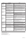
Troubleshooting Guide
Trouble Probable Cause Solution
Screwdriver fails
to rotate (reverse or
forward)
Is there power to the tool?
Defective Power Cord Assembly (6). Replace the Power Cord
Assembly if necessary.
No power from the Controller. Repair or replace (see Controller
Service Manual).
1.
2.
Does the Trigger Switch click when the Trigger
is depressed?
Defective Trigger Switch (8). Replace the Trigger Switch.
Does the Trigger Switch turn on power to
the Motor?
Trigger pad worn. Replace the Trigger (17).
Can the bit be turned by hand when the tool
is unplugged?
Planetary gearing defective. Replace the Planet Gears (39 or
41), Spindle Assembly (40) and Gear Head Assembly (38).
2. Clutch defective. Repair or replace the clutch.
1.
Does the tool operate properly when bumped
and jiggled?
Defective power cord. Replace the Power Cord Assembly (6).
Forward/Reverse Switch defective. Replace the Forward/
Reverse Switch (9).
Defective solder connection.
Check all solder connections; resolder where necessary.
Defective Armature. Replace the Motor Assembly.
Brush contact defective. Replace the Brush Assembly.
1.
2.
3.
4.
5.
Does brush wear appear normal?
Worn or defective Brushes. Replace the Brush Assemblies (24).
Defective Commutator. Replace the Armature (31).
1.
2.
Does motor appear to be in good condition?
Carbon buildup or dirt on Armature (31).
Clean the Armature using a good electrical contact cleaner
and blow dry.
1.
2.