


23
MAINTENANCE SECTION
A thread locking compound was applied to the
threads of the Rotor during assembly to prevent
the Controller Assembly (22) from loosening
during operation. Before attempting to unscrew
the assembly from the Rotor, apply moderate heat
from a propane torch to the middle of the rotor
body to soften the compound. Do not overheat the
Rotor. Heat it only long enough to allow the
Controller Assembly to be unscrewed without
using excessive force.
Use only the special Controller Wrench for
removing the Controller Assembly. Do not attempt
to disassemble the Controller. It is available only
as a unit and is guaranteed for the life of the
Grinder if it is not abused.
11. Using the No. 77H–950 Controller Wrench, unscrew
and remove the Controller Assembly (22).
The Rear End Plate, Spacer and Bearing are a
matched set. Do not mix the components with
those of another set. The Rear Rotor Bearing is
always damaged during the removal process, and a
complete new Rear End Plate Assembly must be
installed.
12. If the Rear End Plate Assembly (23) consisting of the
Rear End Plate, Spacer and Bearing needs to be
replaced, press it from the Controller.
13. Remove the Rear End Plate Gasket (24).
14. Using No. 77H–154 Retainer Pliers, remove the
Throttle Valve Seat Support Retainer (15).
15. Grasp the Throttle Handle horizontally in
leather–covered or copper–covered vise jaws. Using
a brass rod 8” (204 mm) long inserted into the air
inlet end of the handle, lightly tap the brass rod with a
soft hammer to release the Throttle Valve Seat
Support Assembly (8).
16. Remove the Valve Seat Screw (9), Valve Seat Lock
Washer (10), Valve Seat Washer (11), Valve Seat (12)
and Valve Support Seals (13).
17. Check the Oiler Feeder Plug (14). Replace if
necessary.
Disassembly of the Bevel Pinion Driver
For GRP15A–02P–7 Models:
1. Lightly tap the Angle Arbor Housing (43) to release
the Bevel Pinion Driver (31).
2. Remove the Internal Gear (32).
3. Remove the Bevel Pinion Driver Bearing (33). This
is a light press fit.
4. Check the Planet Gears (36) and Planet Gear Bearings
(37) for wear. If they need to be replaced, proceed as
follows:
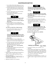
Always remove the Planet Gear Shafts (34) in
the direction shown on the drawing.
a. Using a pin punch and soft hammer, remove the
Planet Gear Shaft.
b. Remove the Planet Gear Assembly.
c. Remove the Planet Gear Bearing from inside
the Planet Gear.
d. Remove the Rotor Pinion (35).
Always replace both Planet Gears even if only
one Planet Gear shows wear.
e. Remove the second Planet Gear as previously
instructed.
5. Unscrew and remove the Pinion (40).
If the Pinion is worn or broken, replace both the
Pinion and Bevel Gear as they are a matched set
and cannot be matched with other Bevel Gears.
6. Press the Bevel Pinion Bearing (39) from the Bevel
Pinion Driver.
7. Remove the Thrust Spacer (38).
For GRG15A, GRG15M or GRS15A Models:
1. Lightly tap the Angle Arbor Housing (43) to remove
the Motor Spacer (41), Arbor Coupling (42), Thrust
Spacer (38), Bevel Pinion Bearing Assembly (39),
and the Bevel Pinion Driver (31).
2. Unscrew and remove the Bevel Pinion (40).
If the Pinion is worn or broken, replace both the
Pinion and the Bevel Gear as they are a matched
set and cannot be matched with other Bevel Gears.
3. Press the Bevel Pinion Bearing (39) from the Bevel
Pinion Driver.
ASSEMBLY
General Instructions
1. Always press on the inner ring of a ball–type bearing
hen installing the bearing on a shaft.
2. Always press on the outer ring of a ball–type bearing
when pressing the bearing into a bearing recess.
3. Whenever grasping a tool or part in a vise, always use
leather–covered or copper–covered vise jaws.
Take extra care with threaded parts and housings.