


25
MAINTENANCE SECTION
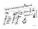
f. Press the Bevel Pinion Driver Bearing (33) onto
the gear head end of the Bevel Pinion Driver (31).
g. Install the Internal Gear (32) over the gear head
end of the Bevel Pinion Driver, making sure the
splines of the Internal Gear mesh with the Planet
Gear teeth.
h. Install the Thrust Spacer (38) over the threaded
end of the Bevel Pinion Driver.
i. Press the Bevel Pinion Bearing (39) onto the
Bevel Pinion Driver.
If the Pinion (40) needs to be replaced, replace
both the Pinion and Bevel Gear. They are a
matched set and cannot be matched with other
Bevel Gears.
j. Check the Pinion for worn or broken teeth.
k. Screw the Pinion onto the threaded Bevel Pinion
Driver and tighten to 14 to 19 ft–lb (19 to 26 Nm)
torque.
For GRG15A, GRG15M or GRS15A Models:
a. Press the Bevel Pinion Bearing (39) over the
threaded end and onto the Bevel Pinion
Driver (31).
If the Pinion (40) needs to be replaced, replace
both the Pinion and the Bevel Gear. They are a
matched set and cannot be matched with other
Bevel Gears.
b. Check the Pinion for worn or broken teeth.
c. Screw the Pinion onto the Bevel Pinion Driver and
tighten to 14 to 19 ft–lb (19 to 26 Nm) torque.
d. Coat the inner surface of the Arbor Coupling (42),
the spline of the Rotor (26) and the spline of the
Bevel Pinion Driver with 3 to 4 cc of
IRAX No. 68–1LB Grease. Do not substitute
any other grease.
e. Install the Arbor Coupling onto the spline end of
the Bevel Pinion Driver.
f. Install the Thrust Spacer (38) over the Arbor
Coupling (42) until it is against the Bevel Pinion
Bearing.
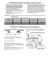
2. Grasp the Angle Arbor Housing (43) horizontally in
leather–covered or copper–covered vise jaws.
3. Slide the assembled Bevel Pinion Driver into the
Angle Arbor Housing.
4. For GRG15A, GRG15M or GRS15A Models, next
install the Motor Spacer (41).
Make sure the Throttle Lever Assembly (17)
mounting boss on the Throttle Handle (1) aligns
with the closed, upper portion of the Angle Arbor
Housing.
For GRP15A–02P–7 Models, make sure the spline
on the Rotor (26) properly engages the spline in the
Rotor Pinion (35).
5. Slide the assembled Throttle Handle into the Angle
Arbor Housing.
6. Clean the Coupling Nut (21) threads and carefully
apply a uniform coat of Vibra–Tite** VC3 No. 205
to at least the first three threads. Allow the
Vibra–Tite to cure for ten to twenty minutes before
assembly.
Do not exceed 52.5 ft–lb (71.2 Nm) torque. The
motor may be damaged if this torque is exceeded.
7. Using the No. 49843–147 Coupling Nut Wrench,
install the Coupling Nut and tighten it between 48 to
52.5 ft–lb (64 to 71 Nm) torque.
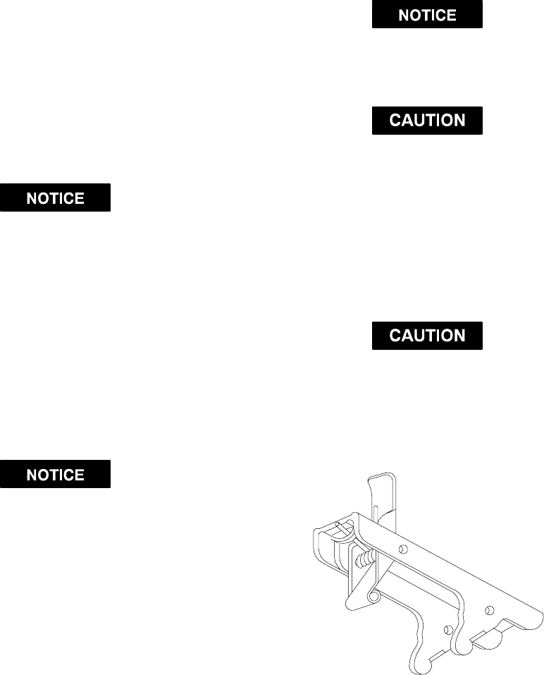
Assembly of the Throttle Lever and Inlet
(Dwg. TPD662)
Locking Lever Assembly
1. Assemble the Throttle Lever Assembly (17) as
illustrated.
2. Align the holes in the Throttle Lever Assembly with
the slots in the Throttle Handle. Using a soft hammer,
tap the Throttle Lever Pin (16) into the Throttle Lever
Assembly until it slightly protrudes from the opposite
end. File off any sharp edges. Operate the
mechanism to assure operation.
3. Grasp the flats of the Throttle Handle Assembly (1) in
leather–covered or copper–covered vise jaws, air inlet
up.
** Registered trademark of N.D. Industries