14
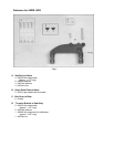
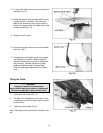
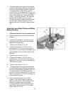
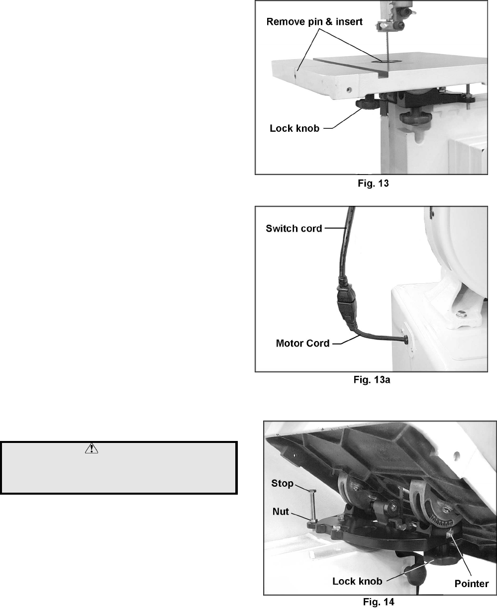
13. To mount the table, remove pin and insert from
the table (Fig. 13).
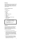
14. Rotate the table so that the saw blade will slide
through the slot in the table. Then orient the
table so the screws will slide into the holes on
the trunnion support brac ket. Attach lock knobs
to these screws (Fig. 13).
15. Replace pin and insert.
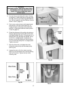
16. Connect the plugs of the motor cord and switch
cord (Fig. 13a).
17. Transportation and handling may have caused
some fasteners to loosen. Before operating,
check all screws, bolts, and nuts to make sure
they are snug. Operate machine only after
reading the entire manual including blade
tracking, blade guide adjustments, and safety
rules.
Tilting the Table
WARNING
Unplug the machine from the power
source before making any repair or adjustment!
Failure to comply may cause serious injury!
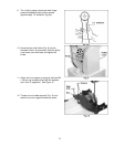
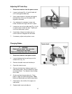
1. Loosen two lock knobs (Fig. 14).
2. Tilt table up to 45 degrees to the right or up to
10 degrees to the left, using the scale mounted
to the trunnion.
3. Tighten two lock knobs (Fig.14).
Note: Table stop must be removed to tilt table to the
left.


