


14
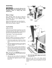
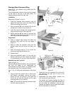
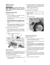
Stamped Steel Extension Wing
Model BTB – the extension wing should look like
(A) in Figure 11
The stamped steel extension wing can be mounted
on the right or left side of the saw table. The
following steps illustrate the right side.
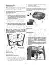
Installation
Referring to Figures 11 and 12:
1. Place the stamped steel extension wing (A)
against the right side of the saw table (B) so
that the mounting holes line up.
2. Place two each M8 lock washers (D) and flat
washers (E) on M8 hex cap screws (C).
3. Insert the screws through the mounting holes
of the extension wing (A) and table (B).
4. Secure with two M8 hex nuts (F) but leave the
assembly loose enough so that the wing can
be moved by hand for adjustment.
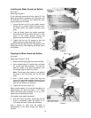
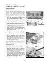
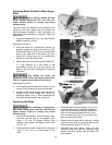
Adjustment
5. Place a straight edge across the table and
extension wing near the front as shown in
Figure 12.
6. Raise or lower the extension wing until the
straight edge lies flat across the table and
wing.
7. Move the straight edge so it lies across the
table and wing towards the back (A).
8. Repeat Step 6.
9. When the extension wing is in line with the
table at the front and rear, tighten the screws
(C) and hex nuts (F) with two 14mm wrenches.
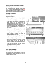
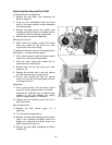
Repositioning the Front Rail
Refer to Figure 13.
After the stamped steel extension wing is installed,
the front rail needs to be repositioned to
accommodate the fence when it is positioned over
the extension wing. This is done as follows:
Item F, Fig. 13 shows the initial position of the front
rail.
1. Using a 5mm hex wrench and a 10mm open
end wrench, completely remove the screw,
spacer and lock nut (shown in the inset) that
secure the rail from the two left and far right
mounting holes (A), (B), and (D).
Note: Do not remove mounting hardware from
the third mounting hole (C).
Figure 11
Figure 12
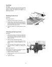
Figure 13
2. Rotate the front rail clockwise (G) until the left
end becomes the right end in front of the
extension wing.
3. Reassemble the three screws, spacers and
lock nuts securing the front rail.
The screws are inserted through the front of
the rail, the spacers are positioned between the
rail and table (or extension), and the lock
washers are fastened to the screw from behind
the lip of the table (or extension).