


21
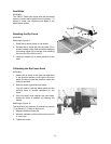
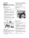
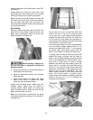
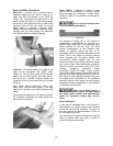
Miter Gauge Operation
Operate the miter gauge by loosening the lock
knob (A, Fig. 25) and turning the miter body
(B, Fig. 25) to the desired angle.
Note: Always make test cuts. Do not rely solely on
miter gauge indicator marks.
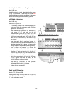
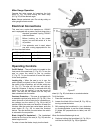
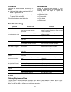
Electrical Connections
This saw has a motor that operates on 120VAC
and is equipped with a power cord that plugs into a
standard grounded 3-prong 120VAC
outlet as shown.
Before hooking up to the power
source, be sure the switch is in the
off position.
If an extension cord is used, select
one with a rating appropriate for the
job from the chart below.
0012 Gauge Cord 000 – 25 feet
0010 Gauge Cord 000 – 50 feet
008 Gauge Cord 000 – 100 feet
Extension Cord Chart
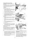
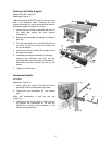
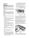
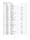
Operating Controls
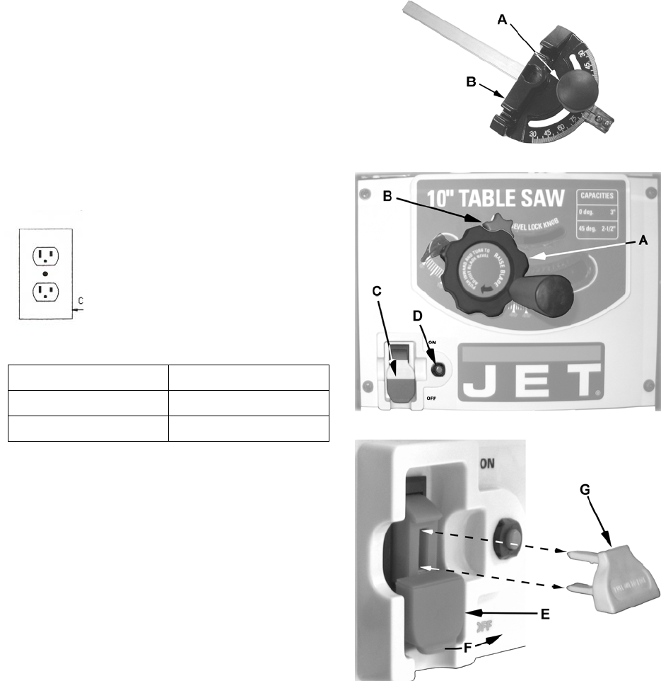
On/Off Switch – The on/off switch is located on the
front panel of the saw base (C, Fig. 26). To turn the
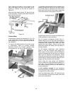
saw on move the switch to the up position
(F, Fig. 27). To turn the switch off move the switch
to the down position.
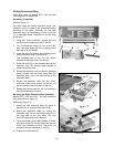
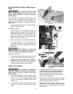
Locking Key – When the saw is not in use, the
switch should be locked in the off position. To lock
the switch in the off position, pull out the safety key
(G, Fig. 27). The saw will not start with the key
removed. However, if the key is removed while the
switch is in the on position, it can be turned off
once. The saw will not restart until the key has
been reinserted into the switch.
Overload Protection – This saw is equipped with
a resetable overload relay button (D, Fig. 26). If the
motor shuts off or fails to start due to overloading or
low voltage, turn the switch (C, Fig. 26) to the off
position and let the motor cool down for at least five
minutes. After the motor has cooled down, push the
reset button (D, Fig. 26) to reset the overload
device. The saw should now start when the switch
is returned to the on position.
Blade Height/Tilt Handwheel – The handwheel
located on the front of the saw (A, Fig. 26) sets the
blade height and tilt.
To raise or lower the blade, simply turn the hand-
Figure 25
Figure 26
Figure 27
wheel (A, Fig. 26) clockwise or counterclockwise.
To tilt the blade:
1. Press the handwheel in.
2. Loosen the blade tilt lock knob (B, Fig. 26) by
turning counterclockwise.
3. Still pressing the handwheel in, turn clockwise
or counterclockwise to set the blade between
0º (blade 90º perpendicular to table) and 45º
(left tilt).
When the desired blade angle is set,
4. Continue holding the handwheel (A, Fig. 26) in
until the lock knob (B, Fig. 26) is tightened.