


16
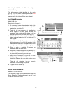
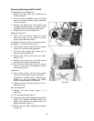
Mounting the Left Extension Wing Assembly
Model LSB only
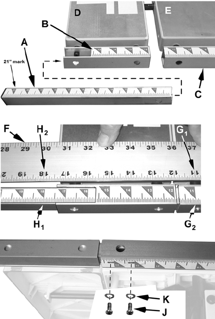
The left extension table, identified by the scale
(B, Fig. 16) on the rail, is used only with model LSB
The assembly and mounting procedure is the same
manner as for the right extension wing (above).
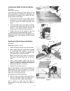
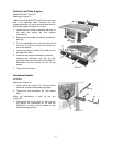
Left Scale Extension
Model LSB only
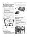
Referring to Figures 16:
1. If necessary, loosen the extension table lock
knobs and slide the extension table (D) flush
against the saw table (E).
2. Take the left rail extension (A) identified by
scale range 11"–21" and insert into the left
extension table guide rail (B), sliding it all the
way through and into the table guide rail (C).
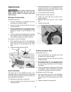
3. View from underneath and adjust until the two
holes in the rail extension (A) and table rail (C)
are aligned.
4. Insert two each M4x10 pan head screws (J),
M4 lock washers (K) and M4 flat washers (L) to
hold the extension rail in place, but leave loose
enough to permit adjustment (following steps).
5. Place a scale or yardstick (F) across the
extension table and saw table.
6. Align the 11" mark on the ruler (G
1
) with the 11"
mark on the guide rail (G
2
) and hold ruler firmly
in place while performing the next step.
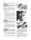
7. Adjust the rail extension (A) until the 18" mark
(H
1
) is aligned with the 18" mark on the
ruler (H
2
). Release the ruler while making sure
the rail extension does not move.
The left rail extension is now properly
calibrated. While holding it in place:
8. Tighten the two screws (K).
Right Scale Extension
Models BTC, LSA and LSB
The assembly steps are the same as for the Left
Scale Extension. For the alignment, use 14" and
21" as the calibration marks.
Figure 16