


11
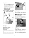
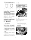
4. Switch the leads in the coolant pump junction
box, according to the diagram in Figure 9. (A
diagram is also included on the coolant pump.)
Figure 9
5. The saw is now ready for 230V operation.
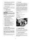
9.4 Grounding instructions
This machine must be grounded. In the event of a
malfunction or breakdown, grounding provides a
path of least resistance for electric current to
reduce the risk of electric shock.
Improper connection of the equipment-grounding
conductor can result in a risk of electric shock. The
conductor with insulation having an outer surface
that is green with or without yellow stripes, is the
equipment-grounding conductor. If repair or
replacement of the electric cord or plug is
necessary, do not connect the equipment-
grounding conductor to a live terminal.
Check with a qualified electrician or service
personnel if the grounding instructions are not
completely understood, or if in doubt as to whether
the tool is properly grounded. Repair or replace a
damaged or worn cord immediately.
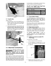
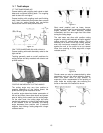
10.0 Adjustments
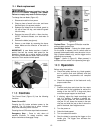
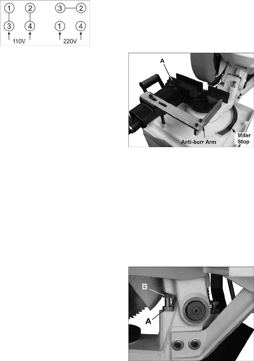
10.1 Miter adjustment
Refer to Figure 10.
The cold saw head has a rotational range of 135°.
To adjust the miter position, follow the steps below:
1. Move the miter position lock lever to the left to
release.
2. Adjust the head to the desired angle by
pushing on the back of the motor to the right or
left. The miter position is shown on the scale.
3. Loosen the cap screw (A) atop the vise, and
slide the jaw as needed to accommodate the
angle of the blade. Re-tighten the cap screw
securely.
4. When the desired cutting angle is set, move
miter position lock lever firmly to the right to
secure the setting.
Two adjustable miter stops are provided for +45
and -45 degrees. Use an angle measuring device
against blade and jaws, or make test cuts to verify
the initial setting of these stops.
10.2 Vise
Refer to Figure 10.
The vise is self-centering and has a cam action
lever for fast clamping. Use the handwheel to move
the vise jaw about 1/16-inch away from the work
piece, then rotate the cam lever to tighten.
The adjustable anti-burr arm keeps the off-cut end
from flexing, which can cause burring. Use a 10mm
hex key to loosen the arm for adjusting.
Figure 10
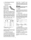
10.3 Stops
Refer to Figure 11.
The front stop limits the blade depth of cut. The rear
stop limits return motion of the head.
To adjust depth of cut:
1. Disconnect machine from power source.
2. Using two 3/4” (19mm) wrenches, loosen lock
nut (A) while holding screw (B) stationary.
3. With the saw in the fully lowered position, turn
screw (B) until the saw blade bottoms out at
the desired level.
4. Tighten lock nut (A).
Figure 11