


9
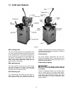
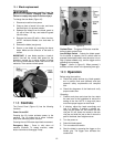
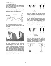
8.1 Operating lever
Refer to Figure 3.
1. Remove the hex nut and screw from the hole
at the front of the saw head (Figure 4). These
fasteners will not be used again unless the
machine needs to be transported in the future.
2. Insert the operating lever into the threaded fill
hole. Rotate it a good distance into the hole,
and make sure the final orientation of the
handle grip is in a comfortable position for the
operator, as shown in Figure 3.
3. Secure the operating lever by tightening the
hex nut against the saw head.
4. Push the two-pin cable connector into the
receptacle sleeve on the junction box of the
motor, and tighten the knurled ring to secure.
Figure 3
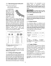
8.2 Handle
Refer to Figure 4.
Screw the handle into the handwheel and tighten
with the nut, using a 12mm wrench.
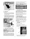
8.3 Exension roller
Refer to Figure 4.
Mount the extension roller to the side with the
existing socket head cap screws, using a 6mm hex
key.
Slots make the roller assembly adjustable for
height. Place a straight edge across the clamp
table and the extension roller to achieve alignment.
Figure 4
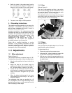
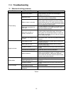
8.4 Coolant tank
Refer to Figure 5.
Direct the lower end of the drain hose into the
basket of the coolant tank, as shown.
Fill the tank with coolant
before operating the coolant pump. Failure to
do so may damage the pump.
Adjust the valve on the coolant fitting atop the
blade housing, to achieve desired flow. When the
coolant switch is in the ON position, flow starts
when the drive motor is started. Turning off the
coolant switch stops coolant flow.
Figure 5
8.5 Splash plates
Refer to Figure 6.
The plates deflect expended coolant and swarf
coming off the blade, into the encircling channel of
the base. The coolant drains back into the tank,
while the swarf is easily cleaned from the channel.
Mount the two plates to the front and rear of the
base, using the existing screws in the base and a
6mm hex key. Slots allow height adjustment.