


1
5
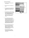
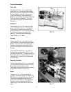
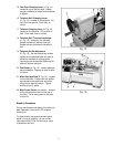
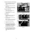
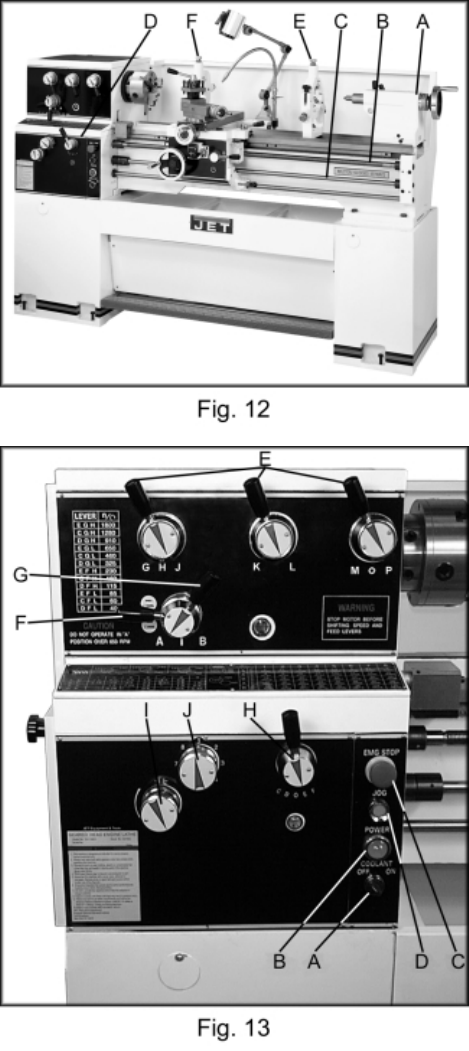
Follow Rest
The traveling follow rest (F, Fig. 12) is
mounted on the saddle and follows the
movement of the turning tool. Only two fingers
are required as the place of the third is taken
by the turning tool. The follow rest is used for
tuning operations on long, slender workpieces.
It prevents flexing of the workpiece from the
pressure of the cutting tool.
The sliding fingers are set similar to the steady
rest, free of play, but not binding. Always
lubricate with Mobil DTE Oil Heavy Medium.
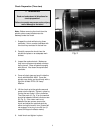
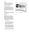
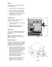
Controls
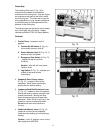
1. Control Panel - located on front of
gearbox.
A. Coolant On-Off Switch (A, Fig. 13) -
turns coolant pump on and off.
B. Power Indicator Light (B, Fig. 13) - lit
whenever lathe has power.
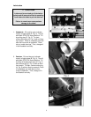
C. Emergency Stop Switch (C,Fig.13)
- depress to stop all machine
functions.
Caution: lathe will still have power.
Twist to re-set.
D. Jog Switch (D, Fig. 13) - depress and
release to advance spindle
momentarily.
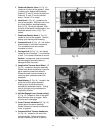
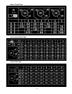
2. Headstock Gear Change Levers
(E, Fig. 13) - located on front of the
headstock. Move levers according to
speed chart for desired setting.
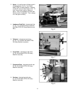
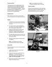
3. Leadscrew/Feed Rod Directional Lever
(F, Fig. 13) - located on front of headstock.
Moving the lever up causes carriage travel
toward the tailstock. Moving the lever
down causes carriage travel toward the
headstock. When chuck is spinning in the
forward or counter-clockwise direction.
Do not move lever while machine is
running.
4. Feed/Lead Selector Lever (G, Fig. 13) -
located on the front of the headstock.
Used whenever setting up for threading or
feeding.
Caution: in the "A" position, never run the
lathe higher than 650 RPM.