


15
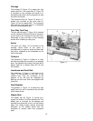
Carriage
The carriage (C, Figure 10) is made from high
quality cast iron. The cross-slide (E, Figure 10)
is mounted on the carriage and moves on a
dovetailed slide which can be adjusted for play
by means of the gibs.
The compound slide (D, Figure 10) which is T-
slotted, and mounted on the cross slide (E,
Figure 10) can be rotated 360°. The compound
slide and the cross slide travel in a dovetailed
slide and have adjustable gibs.
Four Way Tool Post
The four way tool post (F, Figure 10) is mounted
on the compound slide and allows a maximum
of four tools to be mounted at the same time.
Remember to use a minimum of two clamping
screws when installing a cutting tool.
Apron
The apron (G, Figure 10) is mounted to the
carriage. Quick travel of the apron is
accomplished by means of a bed-mounted rack
and pinion, operated by the handwheel on the
front of the apron.
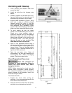
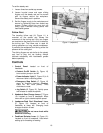
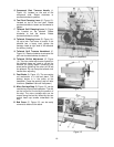
Tailstock
The tailstock (H, Figure 11) slides on a v-way
and can be locked at any location by a clamping
lever. The tailstock has a heavy duty quill with a
Morse Taper #4, or Morse Taper #5 (18” and
22” models).
Leadscrew and Feed Rod
The leadscrew (J, Figure 11) and feed rod (K,
Figure 11) are mounted on the front of the
machine bed. They are connected to the
gearbox at the left and are supported by
bearings on both ends. Both are equipped with
shear pins.
Feed Gearbox
The gearbox (L, Figure 11) is made from high
quality cast iron and is mounted to the left side
of the machine bed.
Steady Rest
The steady rest (M, Figure 11) serves as a
support for shafts on the free tailstock end. The
steady rest is mounted on the bedway and
secured from below with a bolt, nut and locking
plate. The sliding fingers require continuous
lubrication at the contact points with the
workpiece to prevent them from premature
wear.
Figure 11