


17
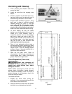
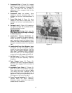
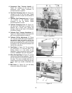
5. Compound Slide (L, Figure 13) is located
on top of the cross slide and can be rotated
360°. There are calibrations in degrees (M,
Figure 13) below the rest to assist in
placement of the compound slide to the
desired angle.
6. Compound Lock (not shown): Lever
located on back of compound slide. Turn
clockwise to lock and counterclockwise to
unlock.
7. Cross Slide Lock (A, Figure 13): Lever
located on left side of cross slide. Turn
clockwise to lock and counterclockwise to
unlock.
8. Carriage Lock (B, Figure 13): Located on
top right of carriage. Turn clockwise to lock,
counterclockwise to unlock.
Carriage lock must be
loose before moving carriage or damage
to lathe may occur.
9. Longitudinal Traverse Handwheel (C,
Figure 13): Located on the apron assembly.
Rotate handwheel clockwise to move the
apron assembly toward the tailstock (right).
Rotate the wheel counterclockwise to move
the apron assembly toward the headstock
(left).
10. Longitudinal/Cross Feed Selector Lever
(E, Figure 13): Can be pushed to upper,
middle and lower three positions. Push the
lever up, cross feed is effected. Push the
lever down, longitudinal feed is effected.
When the lever is in the middle position,
screws can be cut by engaging the half nut.
11. Half Nut Lever (D, Figure 13): Located on
the front of the apron assembly. Used for
threading.
12. Feed Engage Lever (G, Figure 13):
Located in the front of the apron assembly.
Pull lever up to engage. Push lever down to
disengage.
13. Adjustable Feed Clutch (F, Figure 13):
When the machine is overloaded, it can slip.
Then cutting rate must be reduced. Note:
This setting has been calibrated at the
factory and should not need adjustment. If
adjustment ever becomes necessary, follow
the diagram on the front of the apron.
14. Cross Traverse Handwheel (H, Figure 13):
Located above the apron assembly.
Clockwise rotation moves the cross slide
toward the rear of machine.
Figure 13