


16
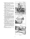
To set the steady rest:
1. Loosen three hex socket cap screws.
2. Loosen knurled screw and open sliding
fingers until the steady rest can be moved
with its fingers around the workpiece.
Secure the steady rest in position.
3. Set the fingers snugly to the workpiece and
secure by tightening three hex socket cap
screws. Fingers should be snug but not
overly tight. Lubricate sliding points with
lead-based grease.
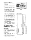
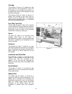
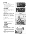
Follow Rest
The traveling follow rest (N, Figure 11) is
mounted on the saddle and follows the
movement of the turning tool. Only two fingers
are required as the place of the third is taken by
the turning tool. The follow rest is used for
turning operations on long, slender workpieces.
It prevents the workpiece from flexing under the
pressure of the cutting tool.
The sliding fingers are set similar to the steady
rest, free of play, but not binding. Always
lubricate adequately with lead-based grease
before operating.
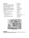
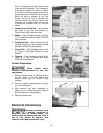
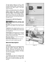
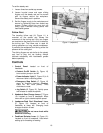
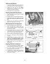
Controls
1. Control Panel: located on front of
headstock.
• Coolant On-Off Switch (A, Figure 12)
turns coolant pump on and off.
• Power Indicator Light (D, Figure 12) is lit
whenever lathe is receiving power.
• Emergency Stop Switch (C, Figure 12)
stops all machine functions (Caution:
Lathe will still have power). Twist
clockwise to re-set.
• Jog Switch (B, Figure 12). Quickly press
and release to rotate the spindle.
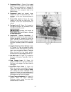
2. Headstock Gear Change Levers (F, Figure
12): Located on front of headstock. Move
levers left or right to desired spindle speed.
3. Leadscrew/Feed Rod Directional Lever
(E, Figure 12): Located on front of
headstock at lower left. Changing knob
changes direction of feed.
Do not move knob while
machine is running.
4. Feed/Lead Selector Lever (H, Figure 12):
Located on front of headstock. Used when
setting up for threading or feeding.
Figure 11 (repeated)
Figure 12