


9
6. Tension the belts (refer to Changing Drive Belt
Position).
7. Check gearbox fluid level in sight gauge. If
required, add lubricant to bring level halfway up
the sight gauge. (Two containers of Shell
Spirax 90 HD gear oil are packed with the saw.
The containers have sufficient amount of
lubricant to fill the gearbox.)
8. Check blade tension and support mechanism
adjustment (refer to Changing Saw Blades).
9. Plug the motor cable into the switch box on the
saw frame. For 3-phase motors, follow the
instructions in the Electrical section to com-
plete the electrical hookup.
NOTE: Observe all electrical codes. Local codes or
difficult environmental conditions may demand spe-
cial electrical hook-ups. Always use a licensed
electrician for any special electrical hook-up.
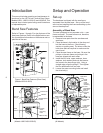
Setting-up Saw
The saw should be bolted securely to the shop floor
to make sure the saw is stable when sawing long,
heavy or unwieldy work pieces. Always use extra
support for long or heavy stock.
There are lugs in the bottom of the saw base for use
in bolting down of the saw. After positioning the saw,
open the door in the base and mark the positions of
the four lug holes. Move the saw to expose the marks.
Prepare for attachment as required by the attachment
method being used. Install the applicalbe fasteners.
Install shims as required to level the saw. Tighten the
fastners to secure the saw to the floor.
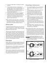
Electrical
Models J-8201 and J-8201VS are delivered with a 115
volt single phase motor. Models J-8203 and J-8203VS
are delivered with a 220/440 volt, 3-phase motor.
When the saw is a 115 volt model, it is supplied with
a standard 115 volt plug and power cord which can be
plugged into any suitable branch circuit.
When the saw is equipped with a 3-phase motor there
will be no plug on the 4-wire cable to the saw switch
box. Instead, follow these instructions to connect the
3-phase motor to the power source:
Connecting to 3-phase power
1. Disconnect and lock out the branch circuit to
the saw before attempting electrical connec-
tions.
2. Connect the green or green-with-white-trace
wire to the branch circuit ground wire.
3. Connect the remaining three wires to the
power wires in the 3-phase branch circuit.
4. Reestablish power in the electrical branch.
5. Turn on power to the saw motor using the
switch.
6. Observe the direction of the blade. It should
be going DOWNWARD, into the slot on the
table. If it is not going downward, the power
wires are hooked-up incorrectly.
7. To correct hook-up, disconnect and lock out
power to the branch, again. Reverse any two
of the power wires on the hook-up to the saw
cable.
8. Reestablish power in the branch and turn the
saw on again. The blade should now be going
downward into the table slot.
Note: local electrical codes or other codes may re-
quire direct connection to a covered, protected junc-
tion box, or other electrical hook-up method. Es-
pecially under difficult industrial conditions, spe-
cialized electrical connections may be necessary.
For special electrical hook-ups, a licensed electri-
cian should be used to connect the saw to power.
CAUTION: KNOW AND OBSERVE ALL LOCAL
AND OTHER APPROPRIATE ELECTRICAL
CODES WHEN ATTACHING THIS BAND SAW
TO YOUR POWER SUPPLY.
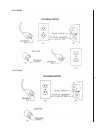
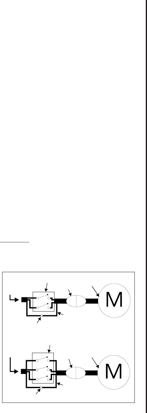
Figure 4: Wiring Diagrams
Green or green
with white trace
1-ph.
power
source
3-ph.
power
source
Motor
Motor
Ground lug
Ground lug
Plug
Plug
Green or green
with white trace
Switch
Switch